Image forming apparatus and image forming apparatus control method

a technology of image forming apparatus and control method, which is applied in the direction of electrographic process apparatus, instruments, optics, etc., can solve problems such as errors, and achieve the effect of preventing unnecessary operations and ensuring safety

Inactive Publication Date: 2011-03-03
KYOCERA DOCUMENT SOLUTIONS INC
View PDF4 Cites 11 Cited by
  • Summary
  • Abstract
  • Description
  • Claims
  • Application Information

AI Technical Summary

Benefits of technology

[0010]In view of the aforementioned problem of the conventional art, it is an object of the invention to reliably prevent excessive temperature rise at a fixing part by turning OFF power distribution to a heater upon passage of a predetermined period of time since disappearance of an interrupt signal regardless of whether a main power source is ON or OFF and also to prevent unnecessary operations from being performed due to failure to stop driving of a control part immediately after the main power source has been turned OFF.
[0012]According to this aspect, the power distribution to the heater is turned OFF upon the passage of the predetermined time since the disappearance of the interrupt signal. Further, the control part, when still driving after the passage of the driving stop time since the disappearance of the interrupt signal, judges that an error has occurred. As a result, even when the main power source has been turned OFF, the control part continues to drive for a certain period of time, thereby permitting prevention of the unnecessary operations from being performed.

Problems solved by technology

Further, the control part, when still driving after the passage of the driving stop time since the disappearance of the interrupt signal, judges that an error has occurred.

Method used


Image

  • Image forming apparatus and image forming apparatus control method
  • Image forming apparatus and image forming apparatus control method
  • Image forming apparatus and image forming apparatus control method

Examples


Embodiment Construction

[0021]Hereinafter, an embodiment of the present invention will be described with reference to FIGS. 1 to 6. Note that elements such as configuration and arrangement described in the embodiment do not limit the scope of the invention and thus simply serve as illustrative examples.

[0022](Outline Configuration of a Multi-Function Peripheral 100)

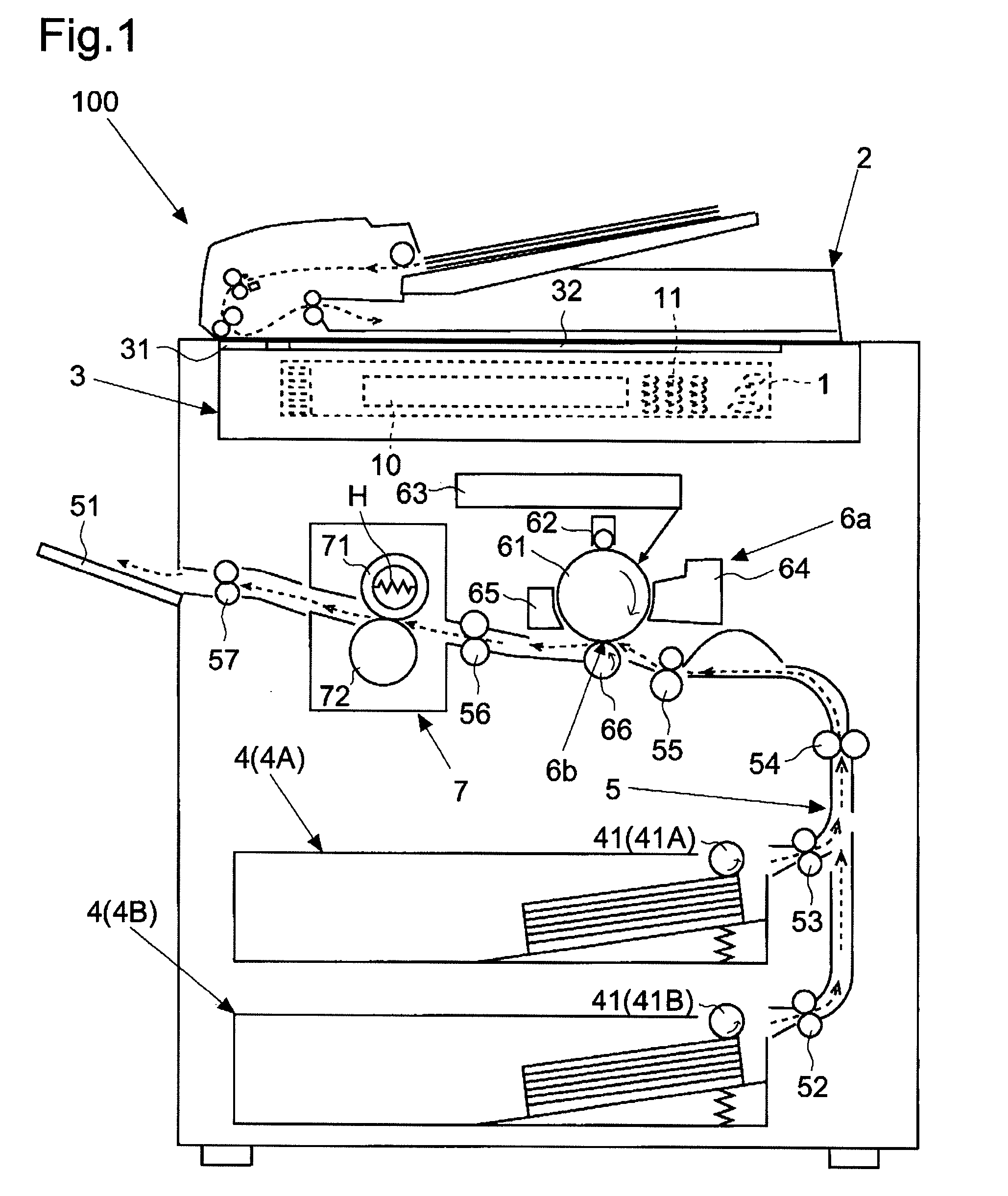
[0023]First, referring to FIG. 1, an outline of a multi-function peripheral 100 (corresponding to an image forming apparatus) of a xerographic, digital type according to the embodiment of the invention will be described. FIG. 1 is a schematic elevation sectional view showing one example of the multi-function peripheral 100 according to the embodiment of the invention.

[0024]As shown by broken lines in FIG. 1, the multi-function peripheral 100 of this embodiment has an operation panel 1 (corresponding to a display part) at the top in an elevation view. The operation panel 1 is provided with: a liquid crystal display part 10 of a touch-panel type d...


PUM


Abstract

An image forming apparatus according to the present invention includes: a fixing part having a heater; a control part controlling ON / OFF of power distribution to the heater; a power source part generating a voltage for driving the control part; a main switch for turning ON / OFF power supply from outside to the power source part; and an interrupt signal generation part generating a periodical interrupt signal. The control part, based on the interrupt signal, controls ON / OFF of the power distribution to the heater, turns OFF power supply to the heater upon passage of predetermined time since disappearance of the interrupt signal, and judges that an error has occurred, when the control part is still driving after passage of driving stop time from when the main switch is turned OFF to when the control part stops its driving since the disappearance of the interrupt signal.

Description

[0001]This application is based upon and claims the benefit of priority from the corresponding Japanese Patent Application No. 2009-201450 filed on Sep. 1, 2009, the entire contents of which are incorporated herein by reference.BACKGROUND OF THE INVENTION[0002]1. Field of the Invention[0003]The invention relates to an image forming apparatus such as a multi-function peripheral, a copier, a printer or a fax machine provided with a fixing part which is provided with a heater heated through power distribution (energization) and which heats a toner image to fix it.[0004]2. Description of Related Art[0005]Typically, a xerographic image forming apparatus (printer, copier, facsimile, or the like) is provided with a fixing part that heats and pressurizes a toner image formed on a sheet to fix it. Moreover, the fixing part is provided with a heater heated through power distribution for the purpose of heating the toner image. A control part or a control unit in the image forming apparatus tur...

Claims


Application Information

Patent Timeline
Patent Type & Authority Applications(United States)
IPC IPC(8): G03G15/00
CPCG03G15/2039G03G15/80
Inventor MOCHIZUKI, MASAYUKI
Owner KYOCERA DOCUMENT SOLUTIONS INC
Why Eureka
Try Eureka