Enhanced fusing of raised toner using electrography

a technology of electrography and toner, applied in the field of raised printing, can solve the problems of significantly reducing manufacturing yield, significant manufacturing challenges and costs, and achieve the effects of reducing equipment energy requirements and costs, and slowing down the process speed of the fuser

Active Publication Date: 2011-03-03
EASTMAN KODAK CO
View PDF4 Cites 12 Cited by
  • Summary
  • Abstract
  • Description
  • Claims
  • Application Information

AI Technical Summary

Benefits of technology

[0007]Accordingly, the invention is directed to an electrographic printing of raised images to selected areas of a receiver member using electrographic techniques so that they are fixed according to the properties of the raised print such as according to the mass per unit area or toner height. In one embodiment, by slowing down the process speed of the fuser to allow for

Problems solved by technology

However, due to limitations on: 1) toner size due to the manufacturing process—typical processes limit toner size average diameter to roughly 30 μm, and 2) the development step in the electrophotographic process—limiting the mass laydown to roughly a double layer of clear toner, the maximum raised letter height for a rich black text at 320% laydown for 8-9 μm (0.5 mg/c

Method used


Image

  • Enhanced fusing of raised toner using electrography
  • Enhanced fusing of raised toner using electrography
  • Enhanced fusing of raised toner using electrography

Examples


Embodiment Construction

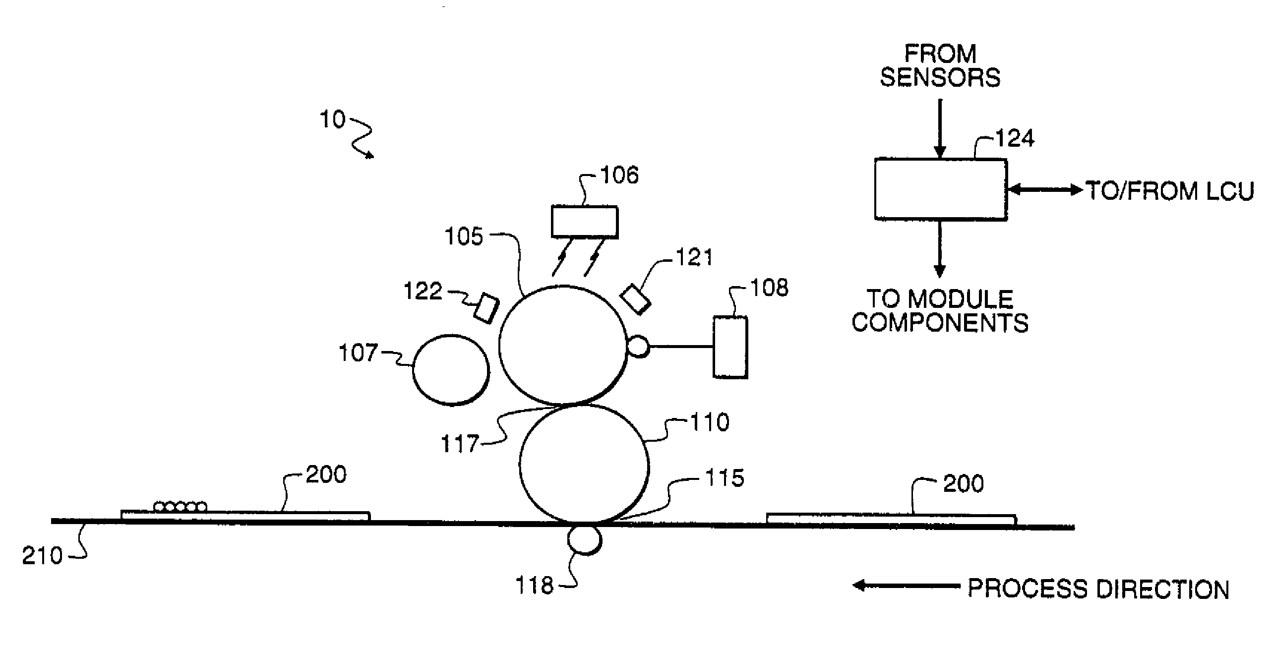
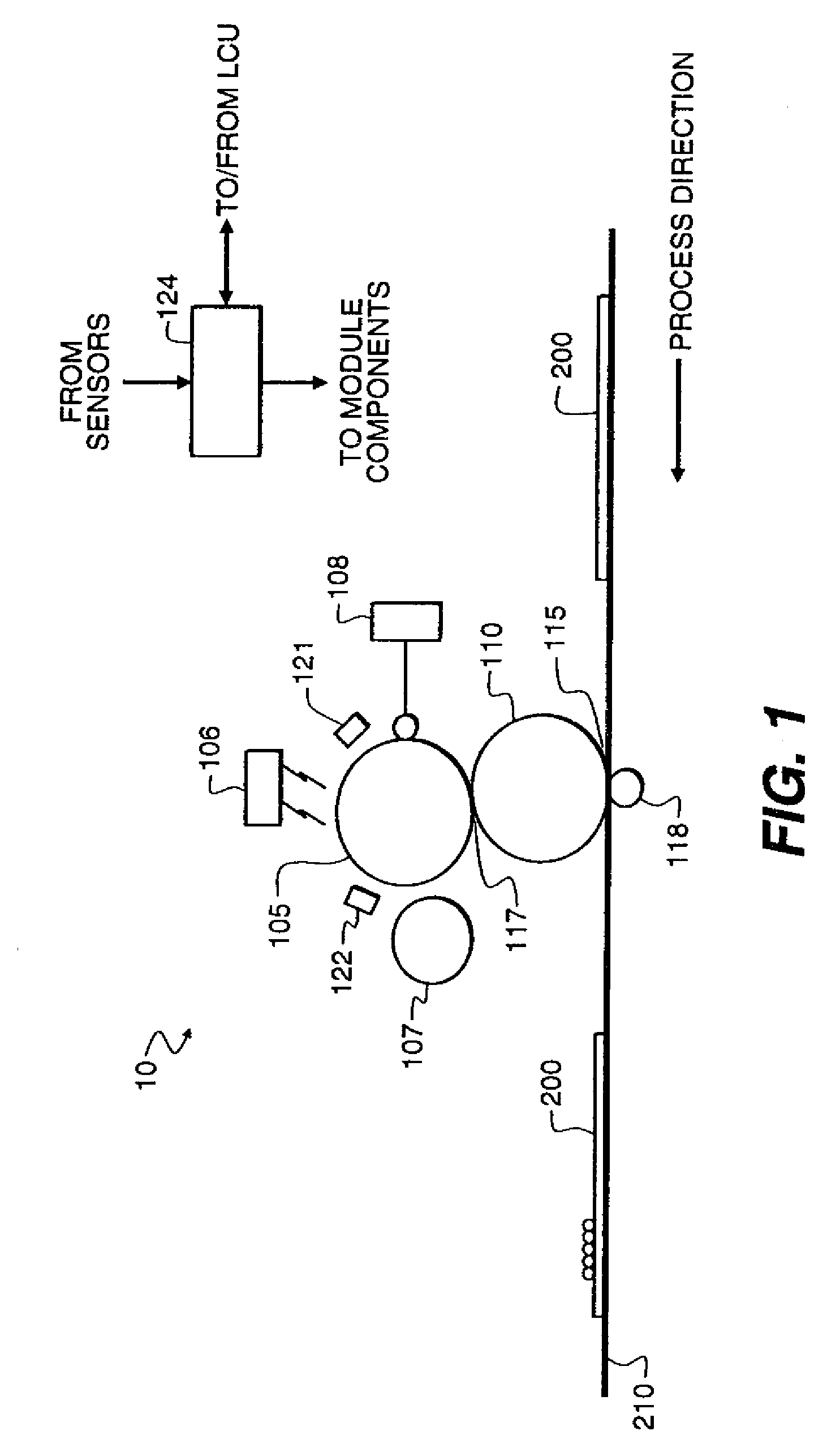
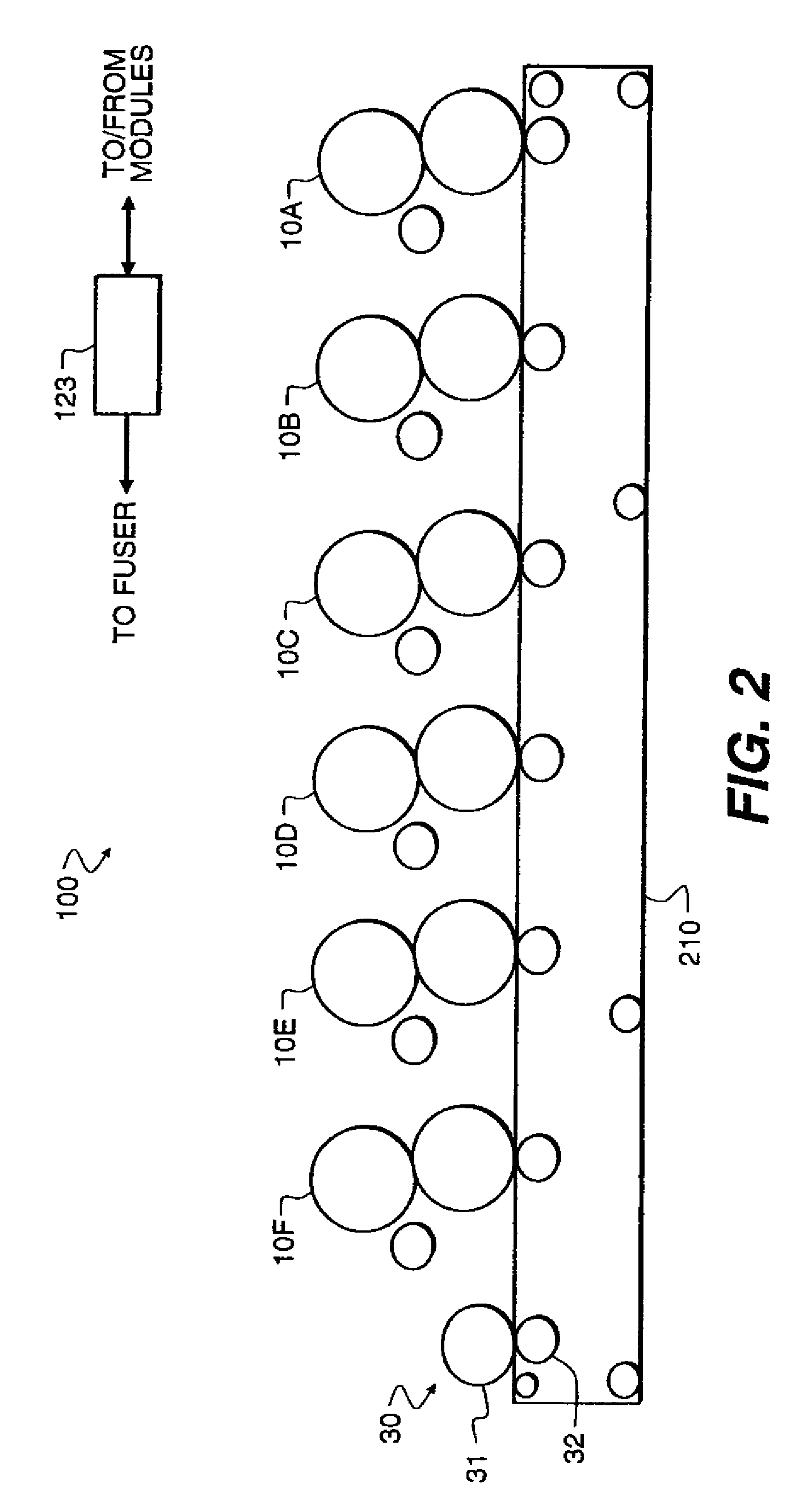
[0014]Referring now to the accompanying drawings, FIGS. 1 and 2 schematically illustrate an electrographic printer engine according to embodiments of the current invention. Although the illustrated embodiment of the invention involves an electrographic apparatus employing six image producing print modules arranged therein for printing onto individual receiver members, the invention can be employed with either fewer or more than six modules. The invention may be practiced with other types of electrographic modules.

[0015]The electrographic printer engine 100 has a series of electrographic printing modules 10A, 10B, 10C, 10D, 10E, and 10F. As discussed below, each of the printing modules forms an electrostatic image, employs a developer having a carrier and toner particles to develop the electrostatic image, and transfers a developed image to a receiver member 200. Where the toner particles of the developer are pigmented, the toner particles are also referred to as “marking particles.”...


PUM


Abstract

Printing of information with a distinct tactile feel can be accomplished by electrographic techniques. Such electrographic printing includes electrographic printing of raised images to selected areas of a receiver member using electrographic techniques so that they are fixed according to the properties of the raised print such as according to the mass per unit area or toner height. In one embodiment, by slowing down the process speed of the fuser to allow for a longer dwell so that the large toner particles and/or toner mass needed to make raised image will properly adhere to the print media without artifacts. To keep the energy requirements and the cost of the equipment down a speed switching technique is used that slows the process speed of the fuser so that the raised image is properly fused on a wide range of paper types.

Description

FIELD OF THE INVENTION[0001]This invention relates in general to printing and in particular to raised printing to generate a tactile feel using electrographic methods.BACKGROUND OF THE INVENTION[0002]One common method for printing images on a receiver member is referred to as electrography. In a particular implementation of this method, known as electrophotography, an electrostatic image is formed on a dielectric member by uniformly charging the dielectric member and then discharging selected areas of the uniform charge to yield an image-wise electrostatic charge pattern. Such discharge is typically accomplished by exposing the uniformly charged dielectric member to actinic radiation provided by selectively activating particular light sources in an LED array or a laser device directed at the dielectric member. After the image-wise charge pattern is formed, the pigmented (or in some instances, non-pigmented) toner particles are given a charge, substantially opposite the charge patter...

Claims


Application Information

Patent Timeline
IPC IPC(8): G03G15/20
CPCG03G2215/2045G03G15/2064
Inventor TOMBS, THOMAS N.ASLAM, MUHAMMED
Owner EASTMAN KODAK CO
Why Eureka
Try Eureka