
Pump with magnetic bearings

a magnetic bearing and pump technology, applied in the direction of positive displacement liquid pump, piston pump, liquid fuel engine, etc., can solve the problems of high operating cost, high operating cost, and high maintenance cost of bfs

Inactive Publication Date: 2011-03-03
FMC TECH INC
View PDF59 Cites 67 Cited by
  • Summary
  • Abstract
  • Description
  • Claims
  • Application Information

AI Technical Summary

Problems solved by technology

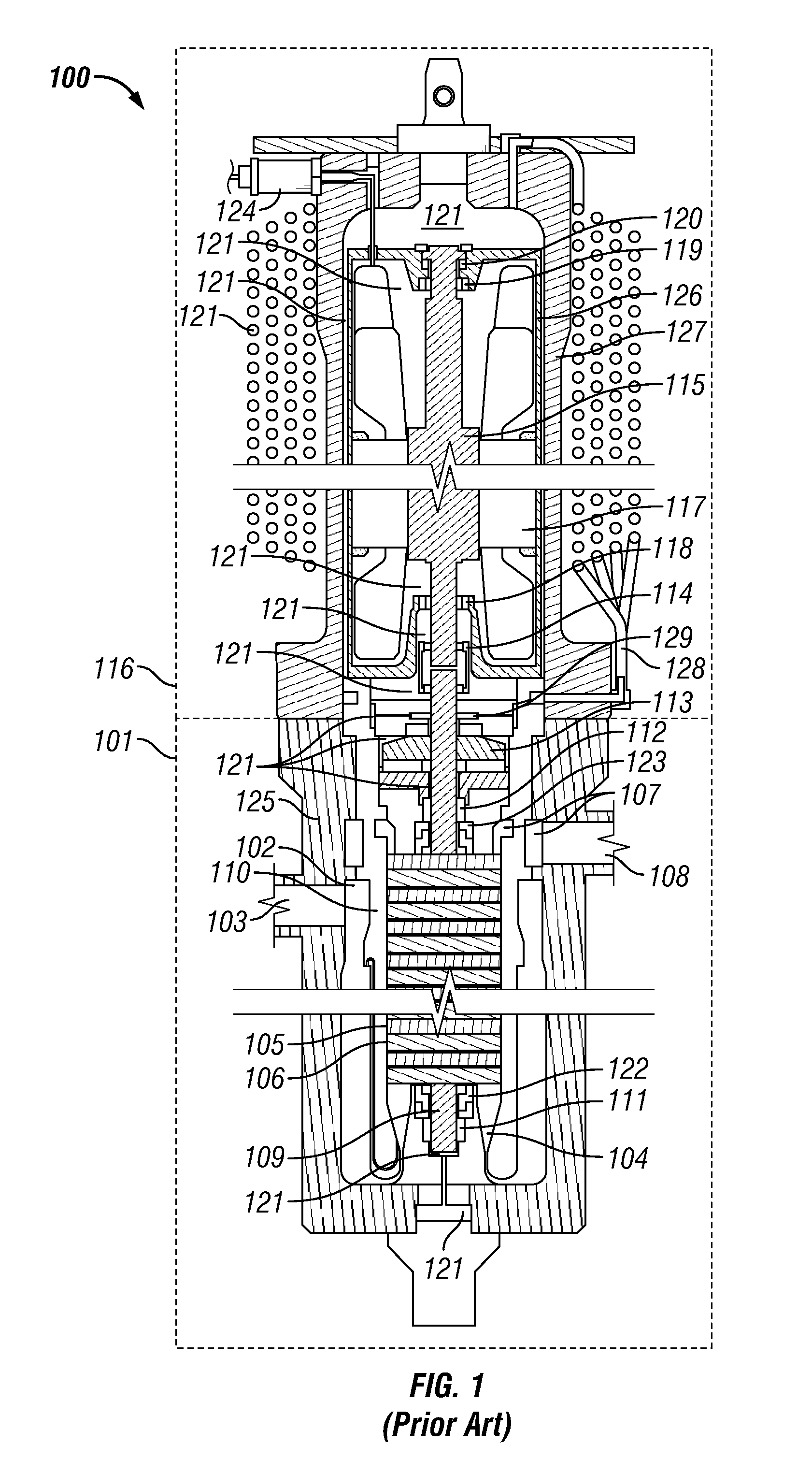
Because the mechanical seals 122,123 leak barrier fluid, the BFS must periodically be resupplied, resulting in undesirable monitoring and maintenance activities that directly increase operating expense.
Furthermore, depending on the specific features of a supplier's motor design, the BFS may suffer an onerous requirement to be maintained dehydrated to a high-specification level.
Damage resulting in system failure will occur quickly if heat beyond design capacity is not removed from the system.
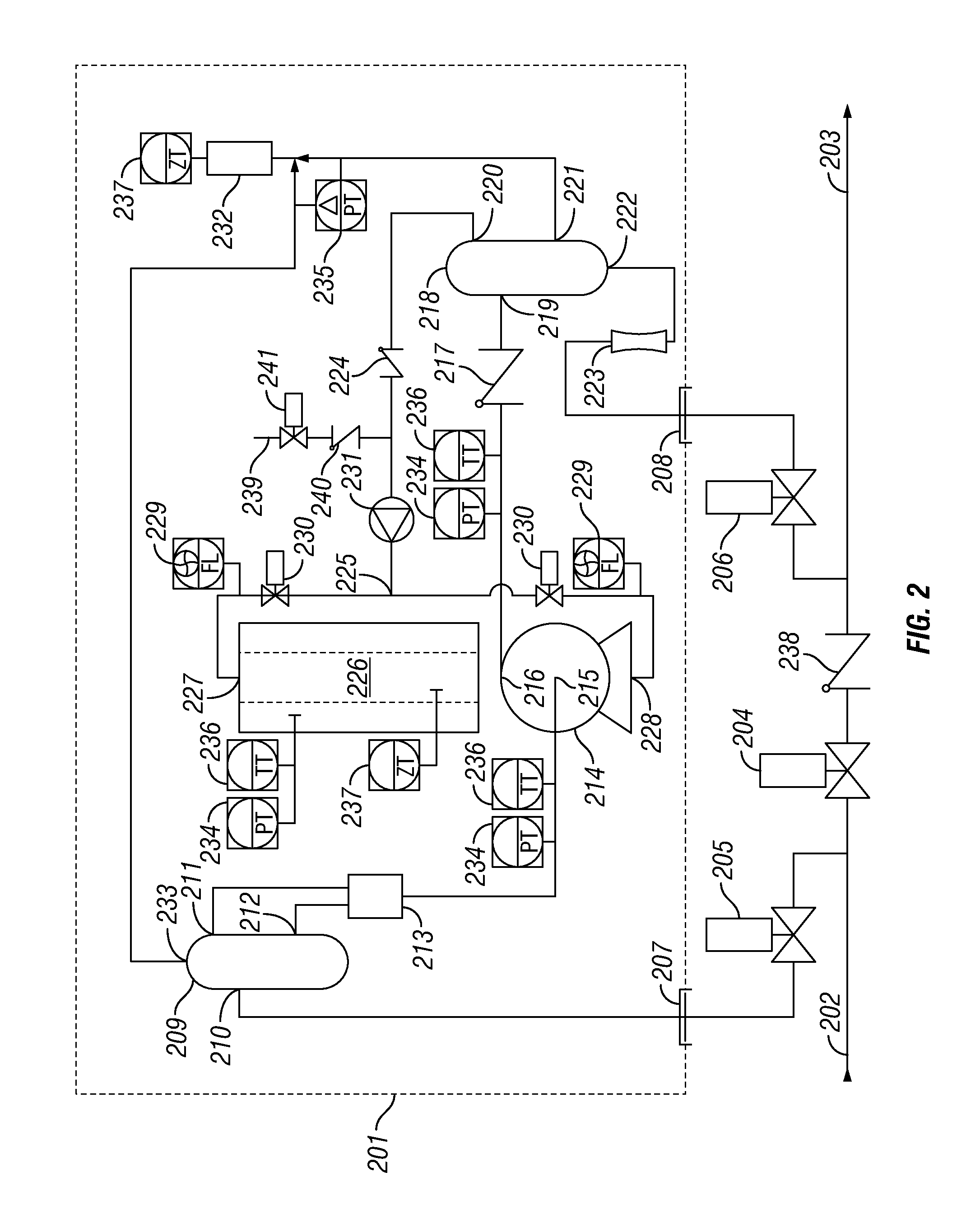
Because several of these components are critical to the correct functioning of the system and therefore the integrity and reliability of the associated subsea pump, redundant such components are typically provided for each field application.

Method used


Image

  • Pump with magnetic bearings
  • Pump with magnetic bearings
  • Pump with magnetic bearings

Examples


Embodiment Construction

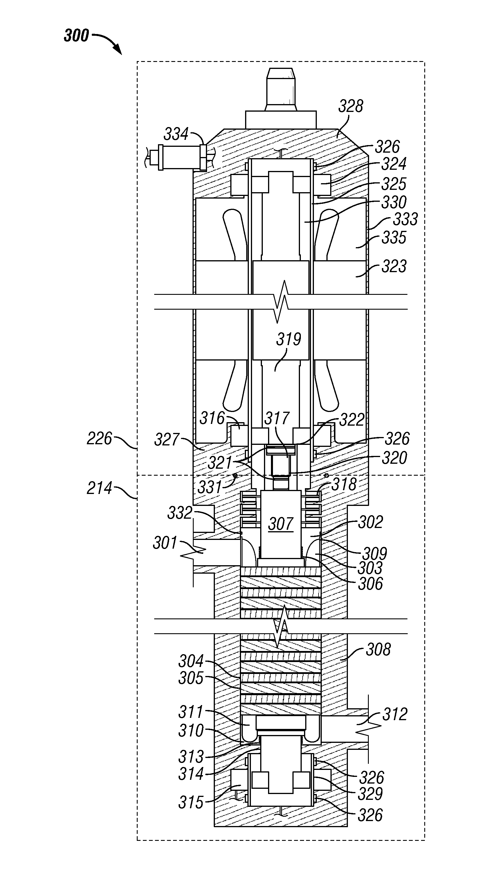
[0023]One or more specific embodiments of the disclosed subject matter will be described below. It is specifically intended that the disclosed subject matter not be limited to the embodiments and illustrations contained herein, but include modified forms of those embodiments including portions of the embodiments and combinations of elements of different embodiments as come within the scope of the following claims. It should be appreciated that in the development of any such actual implementation, as in any engineering or design project, numerous implementation-specific decisions must be made to achieve the developers' specific goals, such as compliance with system-related and business related constraints, which may vary from one implementation to another. Moreover, it should be appreciated that such a development effort might be complex and time consuming, but would nevertheless be a routine undertaking of design, fabrication, and manufacture for those of ordinary skill having the b...


PUM


Abstract

A pump unit includes a motor, a pump, a shaft spanning the motor and the pump, and at least a first magnetic bearing supporting the shaft. A hydrocarbon production system includes an underwater well and a pump unit exposed to an underwater environment. The pump unit is operable to pump a production fluid from the well and includes a motor, a pump, a shaft spanning the motor and the pump, and at least a first magnetic bearing supporting the shaft.

Description

BACKGROUND OF THE INVENTION[0001]1. Field of the Invention[0002]The disclosed subject matter relates generally to a pump with magnetic bearings.[0003]2. Description of the Related Art[0004]Electrically driven pumps have been in common use for many years. One application of such an electrically driven pump is in the field of hydrocarbon service, where subsea pumps may be used. Subsea pumps have been used to pump multiphase fluids, typically including any pump-able combination of oil, gas, water and / or solids, as well as single-phase fluids, e.g. water and / or oil. Conventionally, one of three subsea pump / motor technologies are typically deployed subsea on commercial applications. Two technologies may be characterized as having a “short-fat” induction motor driving a relatively short rotor-dynamic pump (e.g., up to 14 stages), or driving a twin-screw positive displacement pump, which is also relatively short. Typically, rotor-dynamic pumps have been oriented vertically with the inducti...

Claims


Application Information

Patent Timeline
Patent Type & Authority Applications(United States)
IPC IPC(8): F04D13/08H02K7/09
CPCF04D13/10F04D29/48F16C32/0489H02K7/09H02K7/083F04D29/048
Inventor CUNNINGHAM, CHRISTOPHER E.FANTOFT, RUNEHOLLINGSAETER, TERJE
Owner FMC TECH INC
Learn More