Movable platen support mechanism

Active Publication Date: 2011-03-03
FANUC LTD
View PDF6 Cites 10 Cited by
  • Summary
  • Abstract
  • Description
  • Claims
  • Application Information

AI Technical Summary

Benefits of technology

[0019]According to the present invention, there may be provided a movable platen support mechanism of an injection molding machine, which comprises a linear guide unit for guiding the movement of a movable platen in a die closing direction, the movable platen support mechanism having a function to absorb deformation of the movable platen caused by thermal expansion and a function to adjust the horizontal tilt of the movable platen.

Problems solved by technology

If the linear guide is used to guide the movable platen, as described above, a load produced by the deformation of the movable platen acts on the linear guide, thereby greatly affecting the life performance of the guide.
If the linear guide is used to guide the movable platen, as mentioned before, a load produced by the deformation of the movable platen acts on the linear guide, so that the life performance of the guide is greatly affected.
In this case, however, an expensive material with a low linear expansion coefficient needs to be used for a platen, such as a movable platen, and a platen support member, thus entailing an increase in the manufacturing cost of an injection molding machine.
Thus, this technique is not applicable to parallelism adjustment.
According to the technique disclosed in Japanese Patent Appliation Laid-Open No. 2004-330449, the buffer members are mounted vertically and horizontally, so that the posture of the movable platen is unstable and requires support by tie-bars.
Thus, the effect of the linear guide unit to improve the die opening / closing accuracy is small.
Since the adjustment of the parallelism of the platen is not taken into consideration, moreover, this technique is not applicable to the parallelism adjustment.

Method used


Image

  • Movable platen support mechanism
  • Movable platen support mechanism
  • Movable platen support mechanism

Examples


first embodiment

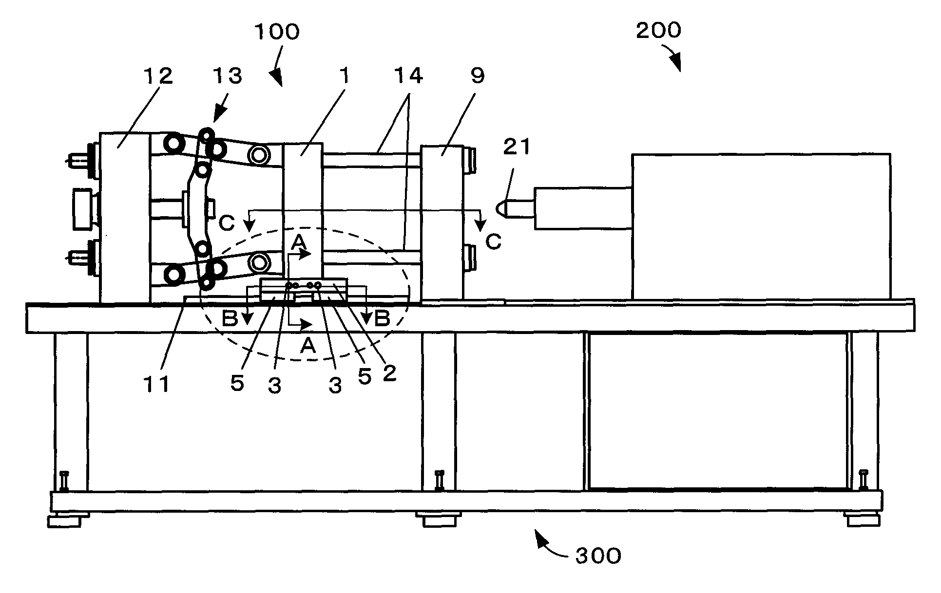
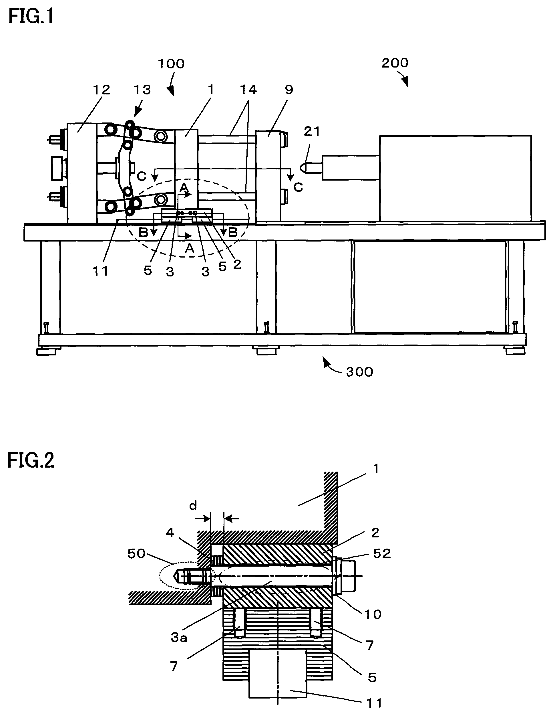
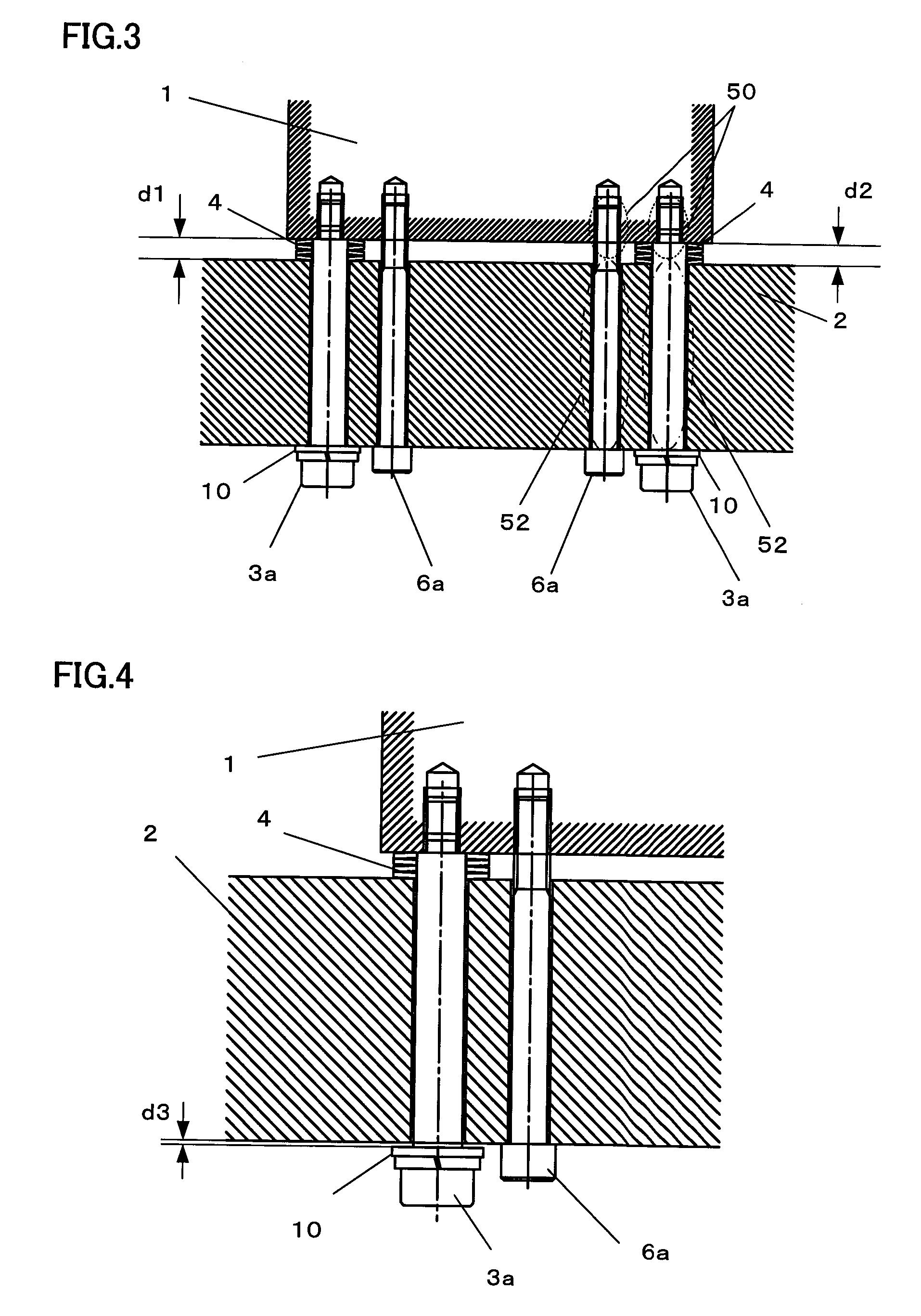
[0036]Referring now to FIGS. 2 and 3, there will be described a first embodiment of a movable platen support mechanism according to the present invention, in which a movable platen 1 is supported by a guide mounting block 2. FIG. 2 is a sectional view of a part including the guide mounting block 2, the linear guide blocks 5, and their surroundings, taken along arrow A-A of FIG. 1. The guide mounting block 2 and the linear guide blocks 5 of FIG. 1 are assumed to be identical to those of the first embodiment.

[0037]The linear guide blocks 5 are placed on the linear guide rails 11, which are mounted on the base frame 300 (FIG. 1), so as to be movable longitudinally relative to the guide rails 11 (or at right angles to the drawing plane of FIG. 2). The guide mounting block 2 is secured to the linear guide blocks 5 by the fixing female screws 7 and the fixing bolts (not shown). The guide mounting block 2 is provided with a through-hole through which a first mounting bolt 3a is passed.

[003...

second embodiment

[0046]Referring now to the sectional view of FIG. 5, there will be described a second embodiment of the movable platen support mechanism according to the present invention, in which the movable platen 1 is supported by the guide mounting block 2. FIG. 5 is a sectional view of the guide mounting block and the linear guide blocks based on this embodiment, taken along arrow B-B of FIG. 1. A sectional view taken along arrow A-A is the same as the one shown in FIG. 2.

[0047]This embodiment differs from the first embodiment in the configuration of adjust bolts. Each of second adjust bolts 6b used in this embodiment has an external thread on its side surface, and the through-hole of the guide mounting block 2 is formed with an internal thread. The extrusion of the movable platen 1 toward the guide mounting block 2 can be adjusted by adjusting the amount of projection of the tip portion of the second adjust bolt 6b from the guide mounting block 2.

[0048]As mentioned before, the guide mounting...

third embodiment

[0052]Referring now to FIGS. 6 and 7, there will be described a third embodiment of the movable platen support mechanism according to the present invention, in which the movable platen 1 is supported by the guide mounting block 2. In this embodiment, adjust nuts are used in place of the adjust bolts.

[0053]An external thread is formed on the tip portion (indicated by a broken-line ellipse 50 in FIG. 6) of each of second mounting bolts 3b. The tip portion of each second mounting bolt 3b is screwed into an internally threaded hole in the movable platen 1. Further, an external thread is also formed on the head side of each second mounting bolt 3b, and an adjust nut 8 engages with the head-side external thread portion. No thread is formed in that part (indicated by a dash-dotted-line ellipse 52) of each second mounting bolt 3b which is fitted in a through-hole formed in the guide mounting block 2. Thus, the second mounting bolts 3b axially move together with the movable platen 1 if they ...


PUM


Abstract

An injection molding machine is provided with a linear guide block configured to be guided on a linear guide rail and a guide mounting block which is secured to the linear guide block and supports the movable platen. Two mounting bolts and two adjust bolts are disposed individually at two positions, spanning between the movable platen and the guide mounting block. The size of a gap between the movable platen and the guide mounting block is adjusted by independently tightening the adjust bolts, whereby the horizontal tilt of the movable platen is adjusted.

Description

BACKGROUND OF THE INVENTION[0001]1. Field of the Invention[0002]The present invention relates to a movable platen support mechanism used in an injection molding machine provided with a movable platen, stationary platen, rear platen, die clamping mechanism, and linear guide unit for axially guiding the movable platen.[0003]2. Description of the Related Art[0004]As shown in FIG. 11, an injection molding machine usually comprises a die clamping unit 100 and an injection unit 200, which are located on a base frame 300. The die clamping unit 100 includes a movable platen 1, stationary platen 9, rear platen 12, and toggle mechanism 13. A plurality of tie-bars 14 are mounted between the stationary platen 9 and the rear platen 12 so as to penetrate the movable platen 1. The tie-bars 14 are slidable relative to the movable platen 1. The stationary platen 9 is fitted with a stationary die (not shown), and the movable platen 1 with a movable die (not shown).[0005]A pair of linear guide rails 1...

Claims


Application Information

Patent Timeline
IPC IPC(8): B29C45/07
CPCY10S425/127B29C45/1761B30B15/007
Inventor NISHIMURA, KOICHINISHIMURA, NARUHIROSENGA, MASATOSHI
Owner FANUC LTD
Why Eureka
Try Eureka