
Control system for exhaust gas fan system

Active Publication Date: 2011-03-03
STROBIC AIR CORP
View PDF66 Cites 39 Cited by
  • Summary
  • Abstract
  • Description
  • Claims
  • Application Information

AI Technical Summary

Benefits of technology

[0010]In accordance with the present invention a control system is provided for exhaust gas systems of the type described above. The control system may be mounted directly on to the fan plenum so that it can operate one or more of: by-pass damper actuators, stage the fans on multiple fan systems, control the fan drive systems, adjust discharge nozzles, determine the static pressure in the exhaust system, and determine the air flow through the fan. The control system may control one or more of the above exhaust system components in order to maintain a minimum gas exhaust through the exhaust fan while still maintain a minimum discharge velocity to ensure proper operation of the exhaust system. This helps to conserve energy.
[0011]According to one aspect of the invention, the control system maintains the by-pass damper closed when gas flow is above a certain minimum and otherwise opens the by-pass damper to maintain gas exhaust above the minimum. A constant static pressure may be maintained in the exhaust system header by modulating the by-pass damper. By keeping the by-pass damper closed except when it is necessary to open the by-pass damper in order to correctly control airflow, considerable savings in energy may be obtained. In other embodiments, the by-pass damper may be eliminated altogether.
[0013]According to one aspect of the invention, adjustable nozzles may be used to maintain a constant pressure in the exhaust system header. An actuator may be used to change the position of a portion of the outlet nozzle thereby adjusting the nozzle outlet area. Decreasing the nozzle outlet area decreases the flow and increases the velocity of the exhaust air exiting the nozzle. Increasing the nozzle outlet area increases the flow and decreases the velocity of the exhaust air.
[0018]According to another aspect of the invention, at least three fans are mounted on a common plenum. At least one fan is operating and at least one fan is in a standby mode. One of the fans may comprise a redundant fan. In case of failure of one of the fans, the control system may energize a redundant fan for exhaust safety. The controls may provide for cycling and sequencing of the fans.

Problems solved by technology

The improper selection, application, installation, operation, and / or control of the exhaust gas system can cause poor system performance.
This can lead to unsafe recirculation of fumes and exhaust gases, excessive noise, premature maintenance, fan failure, and wasted energy.

Method used


Image

  • Control system for exhaust gas fan system
  • Control system for exhaust gas fan system
  • Control system for exhaust gas fan system

Examples


Embodiment Construction

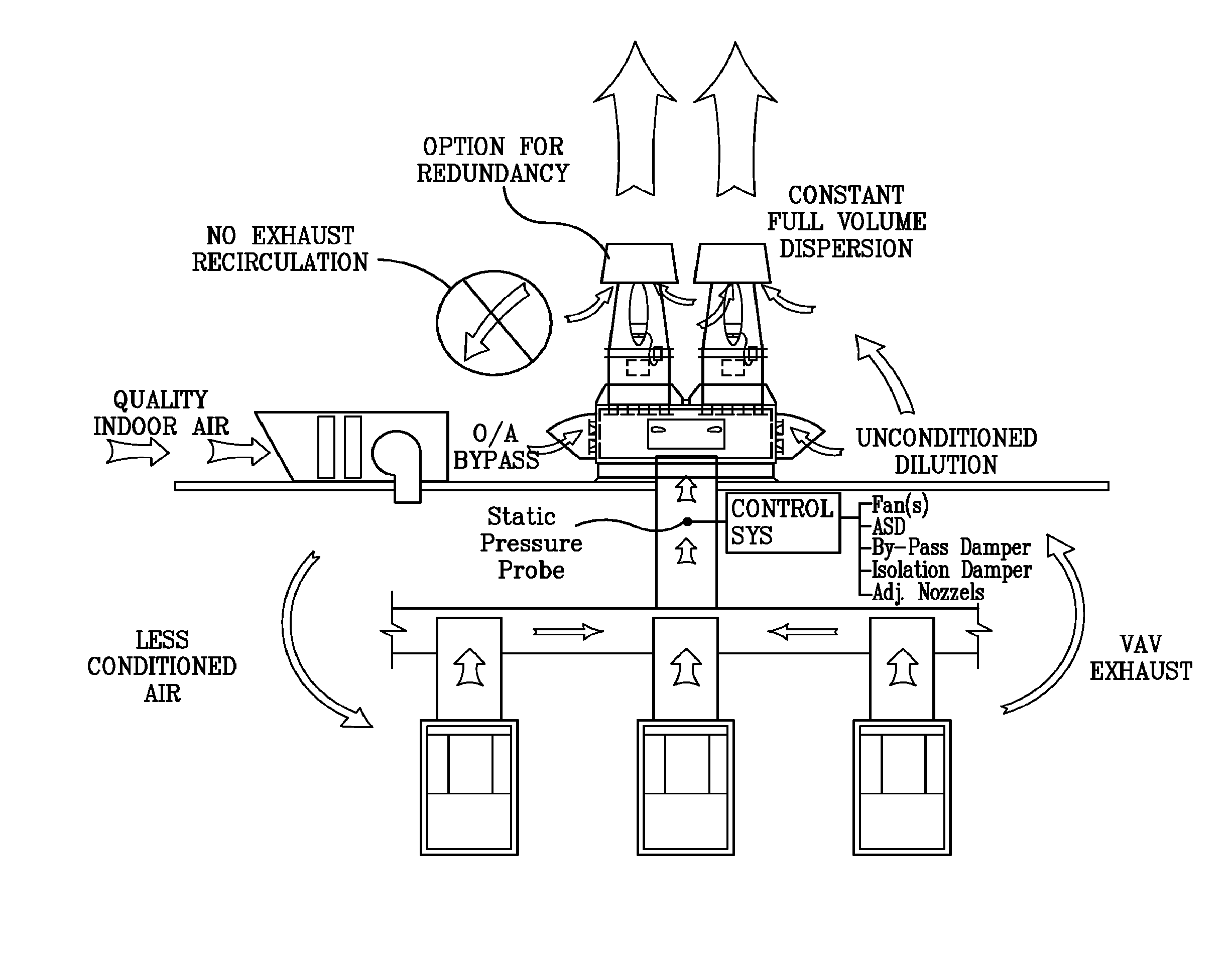
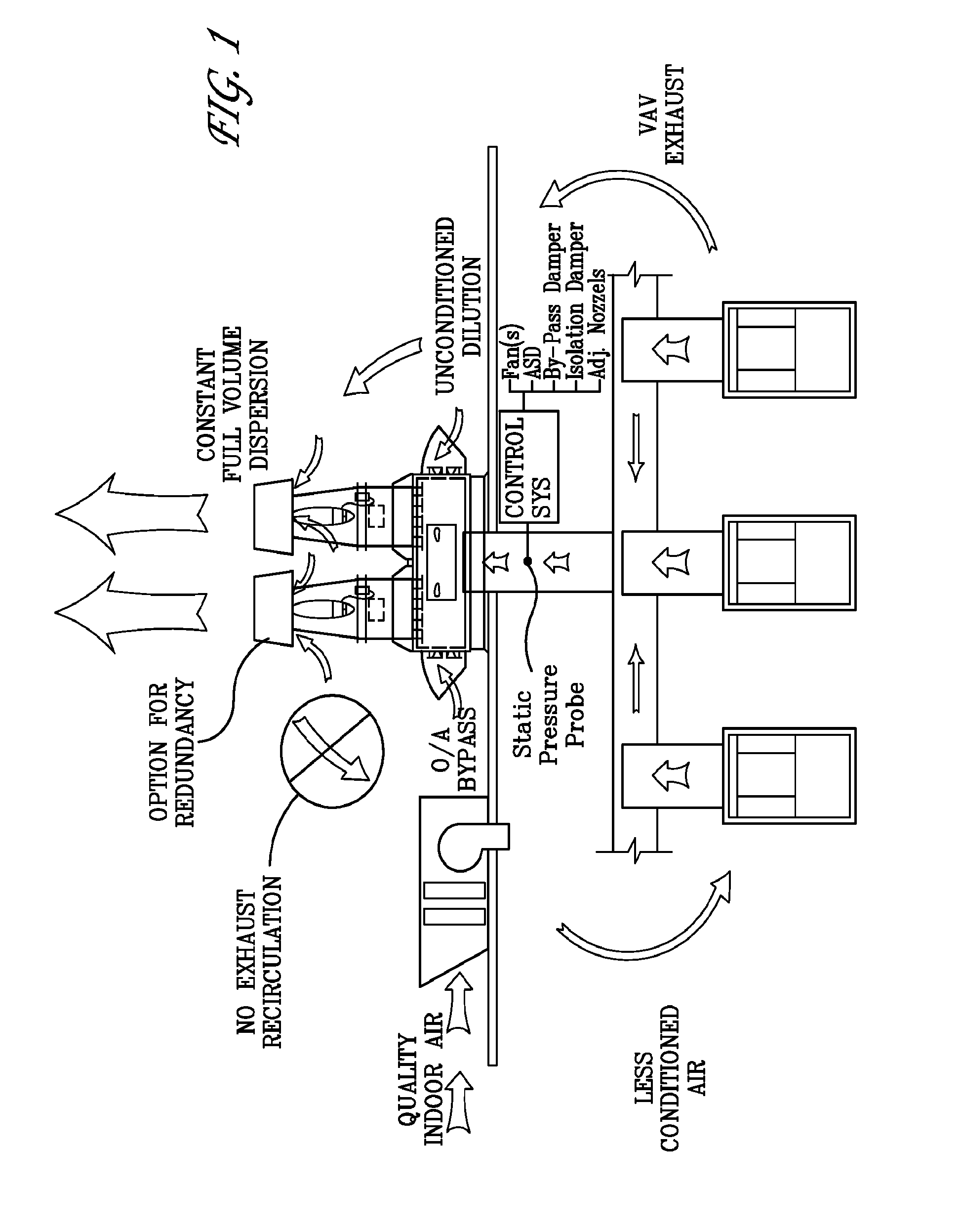
[0033]Embodiments of the present invention are directed to systems and methods for controlling an exhaust gas fan system. The control system may monitor the static pressure of the exhaust system and control one or more components of the exhaust system to optimize system performance and imp rove energy efficiency. The control system may be designed to maintain a substantially constant pressure in the exhaust header and provide a substantially constant flow through the exhaust fans (e.g., a substantially constant volume and discharge velocity). At the same time, the control system may be designed to ensure proper dilution of the exhaust air and to generate an exhaust plume having a velocity sufficient to ensure the exhaust air is not re-introduced into the building intake.

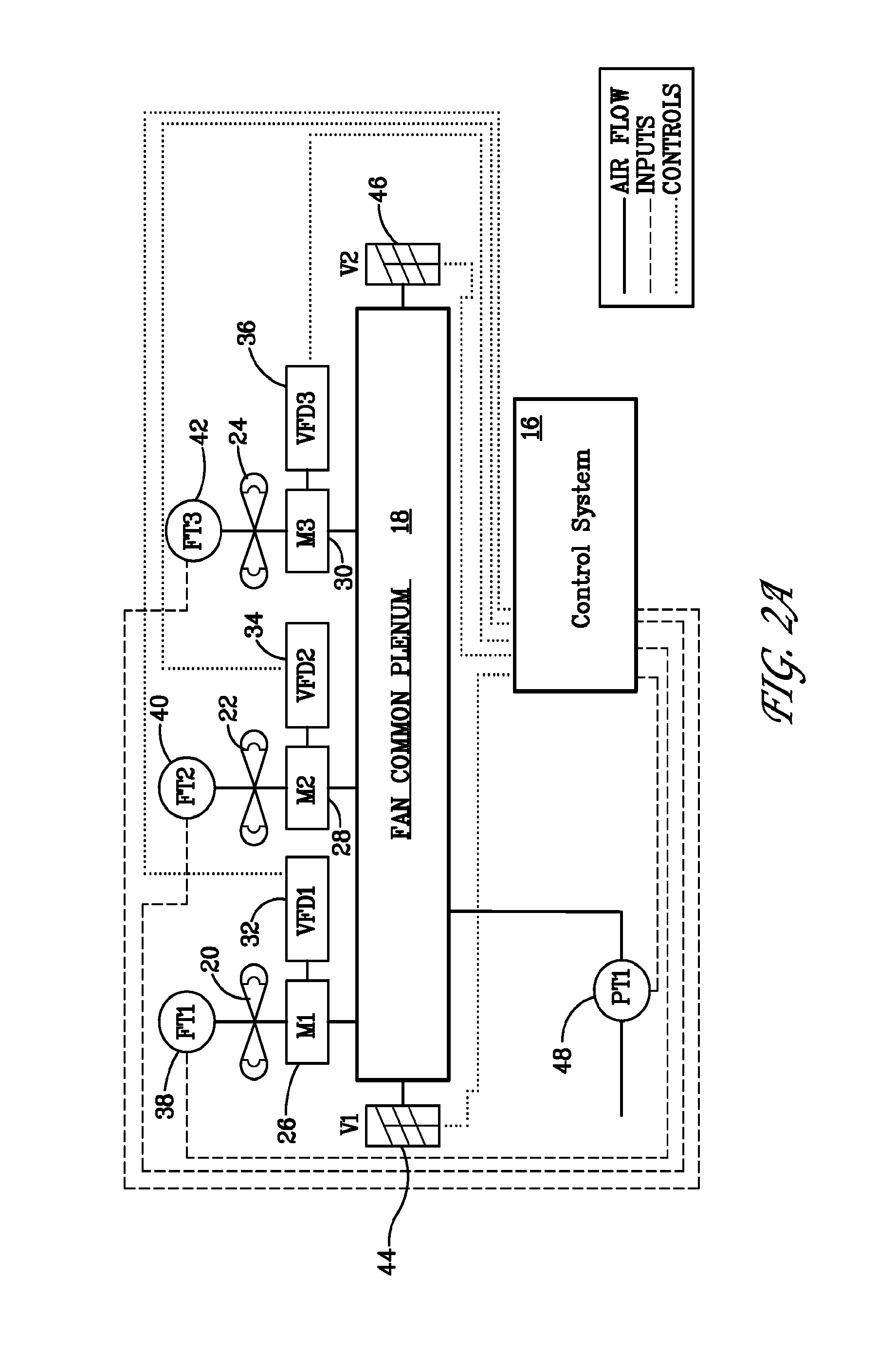
[0034]Embodiments of the present invention tie the control system together with one or more components of the exhaust gas fan system to optimize system performance and provide energy savings. The control system may i...


PUM


Abstract

Systems and methods for controlling an exhaust gas fan system. The control system may control one or more components of the exhaust system to optimize system performance and improve energy efficiency. The control system may be designed to maintain a substantially constant pressure in the exhaust header and provide a substantially constant flow through the exhaust fans. The control system may include software and hardware that allow the control system to control one or more of: modulation of one or more by-pass dampers; adjustment of the nozzle outlet area; varying the speed of the fans; the number and staging of fans. By utilizing and controlling one or more of these functions, the amount of energy being used may be minimized / optimized.

Description

CROSS REFERENCE TO RELATED APPLICATIONS[0001]This application claims benefit of U.S. provisional application Ser. No. 61 / 022,120 filed Jan. 18, 2008, the disclosure of which is incorporated herein by reference in its entirety.TECHNOLOGY FIELD[0002]The present invention relates to building exhaust systems. More particularly, the present invention relates to control systems and methods for controlling gas exhaust fans to exhaust gas from the interior of a building.BACKGROUND[0003]The lifeline of every building ventilation system is the exhaust system. The improper selection, application, installation, operation, and / or control of the exhaust gas system can cause poor system performance. This can lead to unsafe recirculation of fumes and exhaust gases, excessive noise, premature maintenance, fan failure, and wasted energy.[0004]Conventional gas exhaust systems typically have a fan and a nozzle, or a fan and a stack device for pulling gas out of the interior of a building and then conve...

Claims


Application Information

Patent Timeline
IPC IPC(8): F24F7/007
CPCB08B15/002F23L17/005Y02B30/746F24F11/0079F24F7/025F24F2110/40F24F11/77F24F11/72Y02B30/70F24F2140/00F24F13/10F24F13/26
Inventor GANS, CHARLES ALEXANDERTETLEY, PAUL A.MERRITT, BRIAN JAY
Owner STROBIC AIR CORP
Features
  • Generate Ideas
  • Intellectual Property
  • Life Sciences
  • Materials
  • Tech Scout
  • Unparalleled Data Quality
  • Higher Quality Content
  • 60% Fewer Hallucinations
Learn More