Fluid ejection device and method of controlling fluid ejection device

a technology of fluid ejection device and fluid ejection device, which is applied in the direction of fluid jet surgical cutters, liquid handling, instruments, etc., can solve the problems of reducing excision performance, demanding and operability are remarkably reduced, and it is difficult to selectively use the fluid ejection device, etc., to achieve enhanced excision performance, high excision performance, and sufficient performance

Inactive Publication Date: 2011-03-03
COLUMBIA PEAK VENTURES LLC
View PDF7 Cites 21 Cited by
  • Summary
  • Abstract
  • Description
  • Claims
  • Application Information

AI Technical Summary

Benefits of technology

[0016]According to the configuration and the method of controlling of the fluid ejection device in the Application Examples described above, the single fluid ejection device may be used both for the pulsed flow ejection and the continuous flow ejection by switching the fluid ejection therebetween with the ejection command switching unit. Therefore, the operator is allowed to proceed the surgical operation while switching the fluid ejection between the continuous flow ejection and the pulsed flow ejection easily according to the excision characteristics even during the operation.
[0017]Therefore, in the case of the pulsed flow ejection, a high excision performance is obtained at a low flow rate (low pressure), and the surgical operation without being impaired in visibility of the operative site is achieved.
[0018]Also, in the case of the continuous flow ejection, the excision performance is enhanced and the operation adequate to the...

Problems solved by technology

However, it is troublesome to selectively use the fluid ejection devices as occasion demands and operability is remarkably lowered.
However, in this state, a sufficient fluid supply pressure is not obtained and hence the excision pe...

Method used


Image

  • Fluid ejection device and method of controlling fluid ejection device
  • Fluid ejection device and method of controlling fluid ejection device
  • Fluid ejection device and method of controlling fluid ejection device

Examples


first embodiment

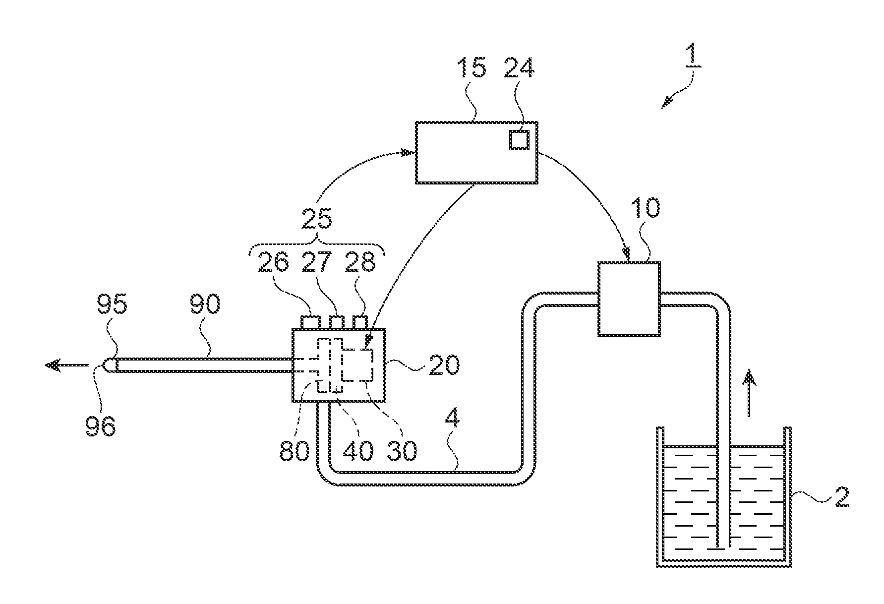
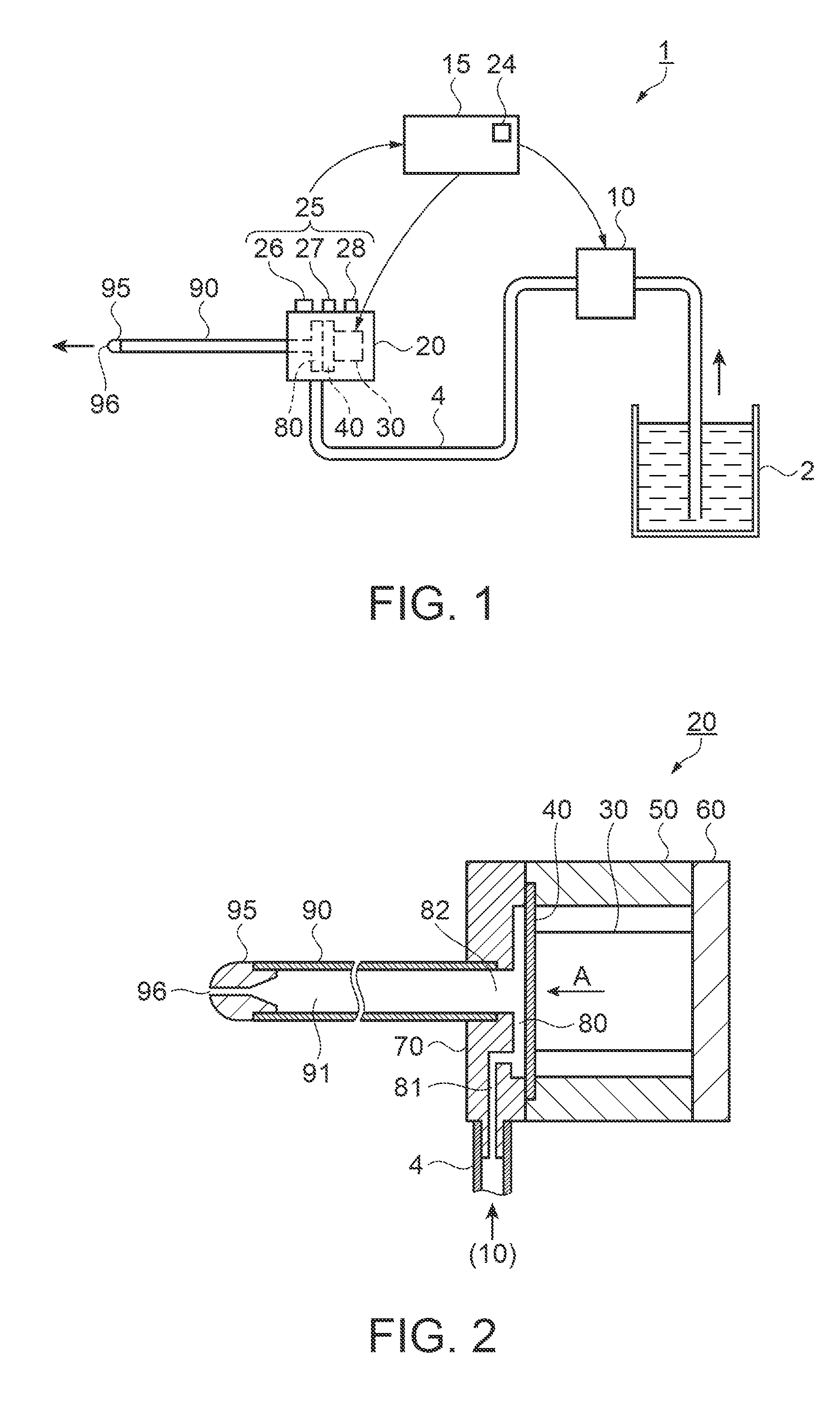
[0029]FIG. 1 is an explanatory configuration drawing showing a fluid ejection device as a surgical instrument according to a first embodiment. In FIG. 1, a fluid ejection device 1 includes a fluid supply container 2 in which fluid is stored, a pump 10 as a fluid supplying unit, a pulsed flow generator 20 configured to transform fluid supplied from the pump 10 into a pulsed flow (hereinafter, it may be referred to as “pulsed flow”), and a drive control unit 15 configured to control drive of the pump 10 and the pulsed flow generator 20. The pump 10 and the pulsed flow generator 20 are connected by a fluid supply tube 4.

[0030]A connecting flow channel tube 90 having a form of a thin pipe is connected to the pulsed flow generator 20. A nozzle 95 having a fluid ejection opening 96 with a reduced flow channel diameter is fixedly inserted to a distal end of the connecting flow channel tube 90. The connecting flow channel tube 90 has rigidity to the extent of not being deformed when the flu...


PUM

PropertyMeasurementUnit
Areaaaaaaaaaaa
Pressureaaaaaaaaaa
Volumeaaaaaaaaaa

Abstract

A fluid ejection device includes: a fluid chamber; a volume varying unit configured to vary the volume of the fluid chamber; a fluid supplying unit configured to supply fluid to the fluid chamber at a predetermined pressure; and an ejection command switching unit configured to switch a fluid ejection between a pulsed flow ejection which ejects the fluid in a pulsed manner by activating the volume varying unit and varying the volume of the fluid chamber and a continuous flow ejection which ejects the fluid with a fluid supply pressure from the fluid supplying unit higher than that in the case of the pulsed flow ejection in a state in which the volume varying unit is stopped.

Description

[0001]This application claims priority to Japanese Patent Application No. 2009-195122, filed on Aug. 26, 2009, and to Japanese Patent Application No. 2010-071012, filed on Mar. 25, 2010, the entirety of which are hereby incorporated by reference.BACKGROUND[0002]1. Technical Field[0003]The present invention relates to a fluid ejection device which allows switching operation between a pulsed flow ejection and a continuous flow ejection, and a method of controlling the fluid ejection device.[0004]2. Related Art[0005]In the related art, there are surgical instruments configured to supply liquid from a pump into a tube introduced into a body cavity at a high pressure, eject the liquid from a nozzle at a distal end of the tube, and excise tissue in the body cavity by a fluid pressure (for example, see JP-A-63-99853).[0006]There is also proposed fluid ejection devices configured to vary the volume of a fluid chamber abruptly by a volume varying unit, transform fluid into a pulsed flow to c...

Claims


Application Information

Patent Timeline
IPC IPC(8): A61B17/3203G01F11/00
CPCA61B17/3203B41J2/14274B41J2/14104B24C1/045
Inventor KOJIMA, HIDEKISUGIMURA, SHIGEOTABATA, KUNIO
Owner COLUMBIA PEAK VENTURES LLC
Why Eureka
Try Eureka