Humeral joint replacement component

US20110054624A1Active Publication Date: 2011-03-03ENCORE MEDICAL

Image

  • Humeral joint replacement component
  • Humeral joint replacement component
  • Humeral joint replacement component

Examples


Embodiment Construction

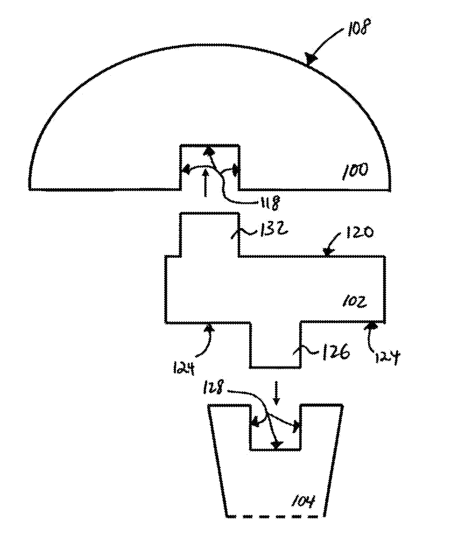
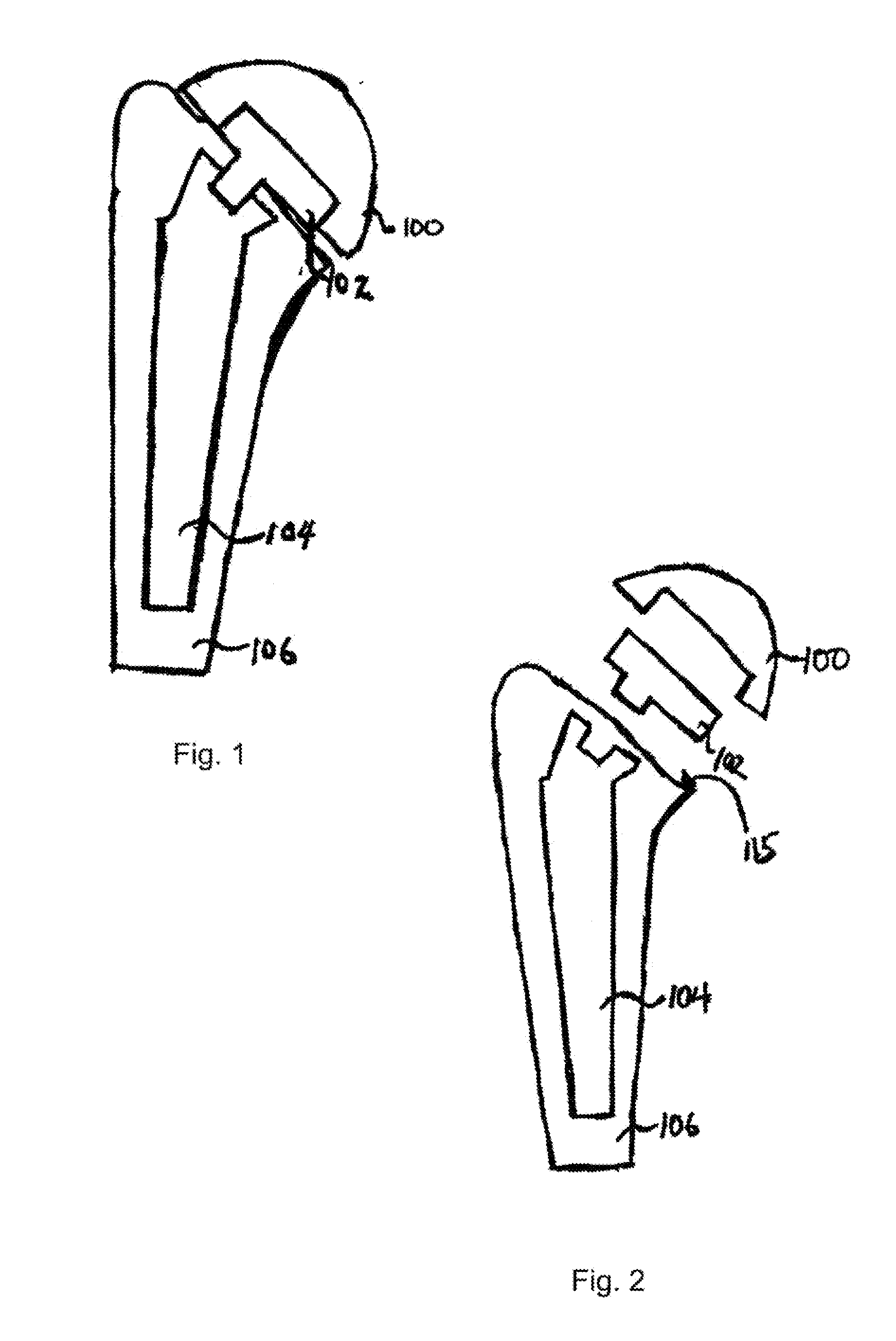
[0058]Referring to FIGS. 1-23A, the present invention provides a humeral prosthetic head 100 having an articulation surface 108 of a semi-ellipsoid that is designed to be in communication with an intermediate component 102. Intermediate component 102 serves as an interface between head 100 and a prosthetic stem 104. Stem 104 is fixed within the metaphyseal and / or diaphyseal part of a humeral shaft 106. This fixation of stem 104 within humeral shaft 106 is achieved by art-disclosed means such as press fit, porous coated biologic fixation, cement fixation, combinations thereof, or other mechanisms. Intermediate component 102 engages with both head 100 and stem 104 as shown in FIGS. 1 and 18.

[0059]The stem 104 can be any art-disclosed prosthetic stem designed to be placed in humeral shaft 106. Stem 104 can be a unitary structure as shown in FIGS. 1-2 and 18. Alternatively, stem 104 can be constructed out of modular components (not shown).

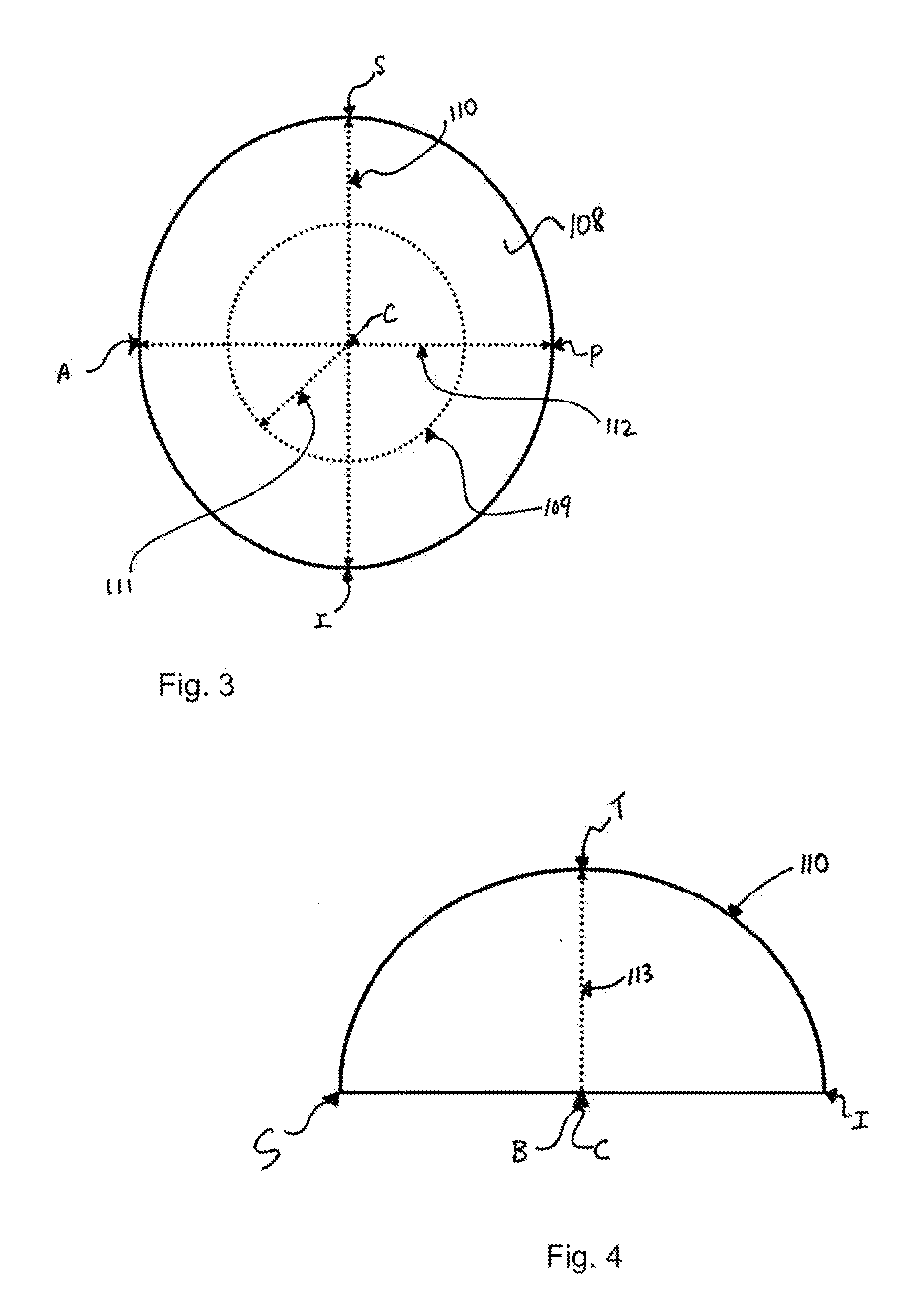
[0060]Referring to FIGS. 3-6, head 100 has artic...


PUM


Abstract

A humeral prosthetic head has a non-spherical articulation surface coupled with an intermediate component connecting the head and the humerus, the intermediate component connected to the epiphysis, metaphysis, or diaphysis, or to one or more additional components connected to the humerus. The intermediate portion provides for axial and angular offset of the head with respect to a connection to the humerus, using a curvilinear tapered engagement.

Description

CROSS REFERENCE TO RELATED APPLICATIONS[0001]This application claims the benefit of U.S. Provisional Application 61 / 238,429, filed Aug. 31, 2009.FIELD OF INVENTION[0002]The present invention relates to the field of joint replacement and / or resurfacing, and more particularly total shoulder arthroplasty or hemiarthroplasty using a stemmed or humeral resurfacing prosthetic.BACKGROUND OF THE INVENTION[0003]Normal shoulder kinematics allows for translational motion of the humeral head within the glenoid particularly at the end ranges of passive motion. These translations can be several millimeters and are thought to be due to capsular tightening on the opposite side of the direction of humeral head translation. Small amounts of translational motion also occur with active range of motion and are correlated with the degree of mismatch in the radii of curvature between the humeral head and glenoid. The native articular surface of the humeral head is not spherical in shape. Nevertheless, it ...

Claims


Application Information

Patent Timeline
03 Mar 2011
Publication
US20110054624A1
IPC
A61F2/40
CPC
C12N2770/24243; C12N15/86; A61F2/4003; A61F2/4014; A61F2/4059; A61F2/4612; A61F2002/30253; A61F2002/30331
Inventors
IANNOTTI, JOSEPH P.