
Network capacity planning

a network and capacity planning technology, applied in the field of network capacity planning, can solve the problems of affecting network performance in a way, complex simulation of transmission characteristics of a network, and complex network topology of network models

Active Publication Date: 2011-03-03
RIVERBED TECH LLC
View PDF3 Cites 23 Cited by
  • Summary
  • Abstract
  • Description
  • Claims
  • Application Information

AI Technical Summary

Benefits of technology

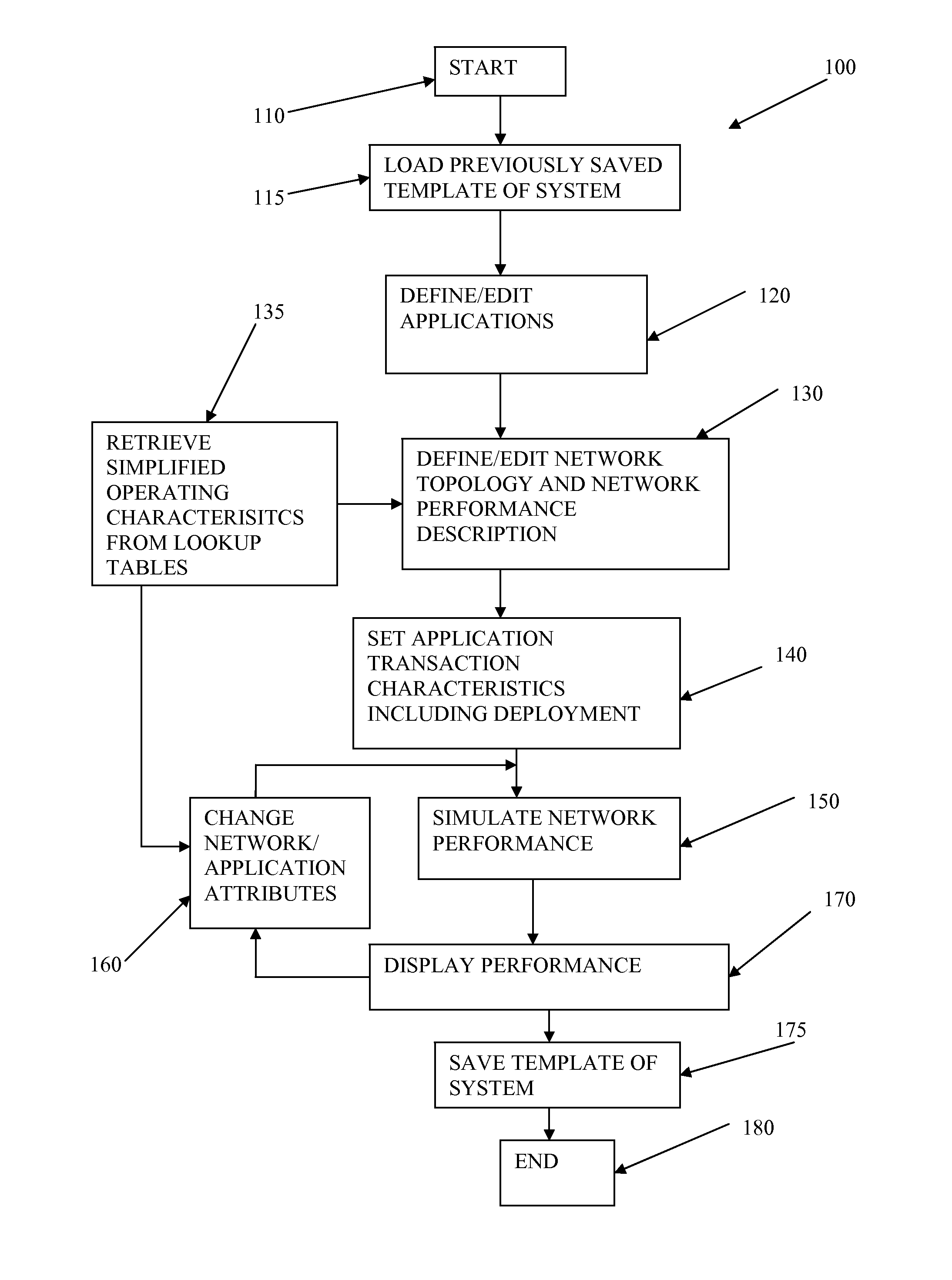
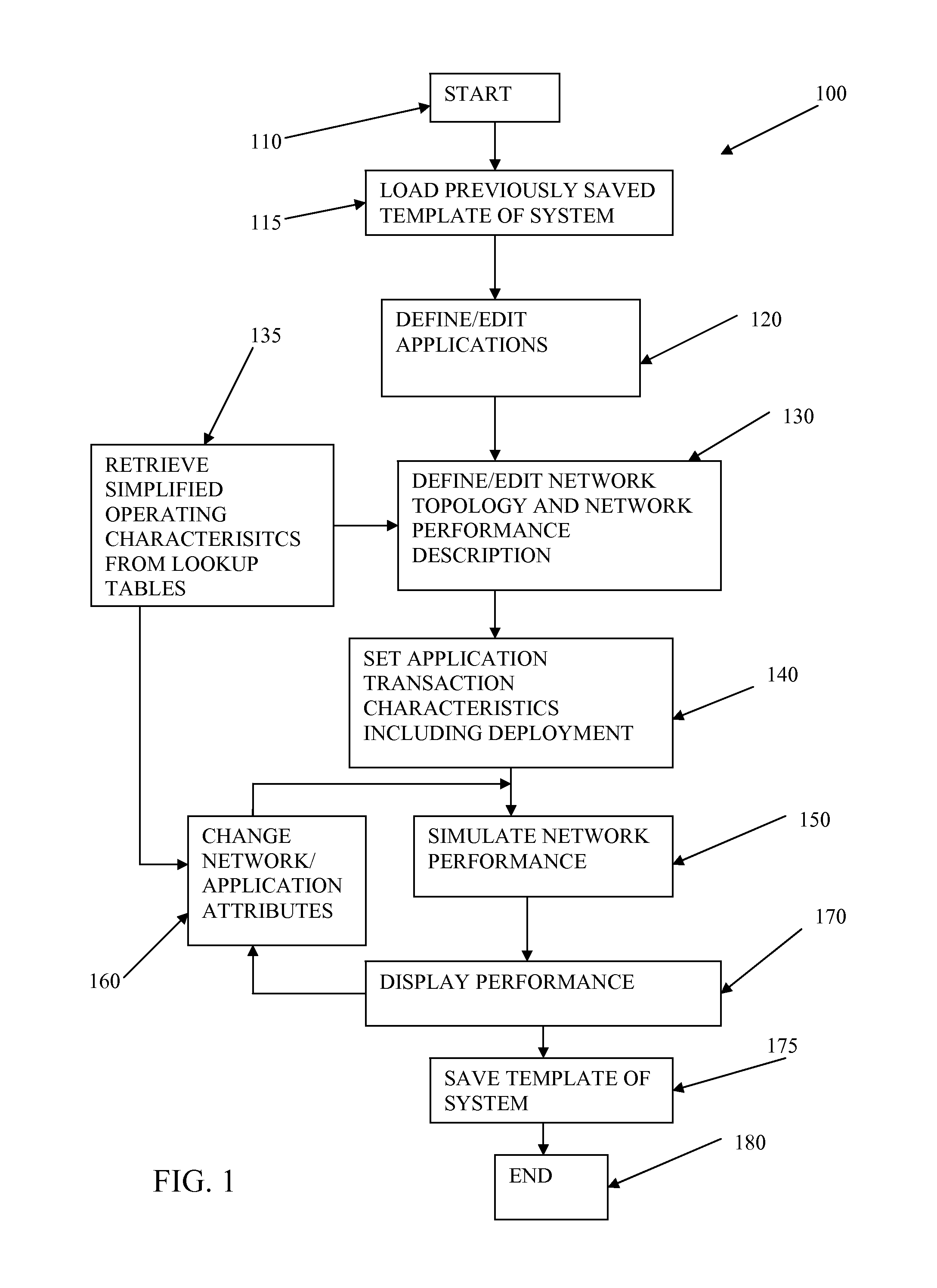
The present system is a simplified system for determining the impact of application deployment on a network. It receives data representing application deployment attributes, network topology, and network performance attributes. The system uses a reduced set of element attributes, such as network boundary values, to interpolate and simulate network performance. The simulation results are displayed as a function of delays attributable to simulation elements. The system can also model queuing delays, congestion on routers, and server delay. The application deployment attributes may include a designation of a number of sites supporting network deployment and each tier of application deployment may be presumed to be selected randomly. The system can also be used to model delay on servers and congestion on a router. Overall, the system simplifies network capacity planning and facilitates application deployment studies.

Problems solved by technology

However, these network models often involve very complex network topology.
Simulation of transmission characteristics of a network are further complicated in that network behavior does not scale linearly with network traffic.
However, as the load increases, for example due to deployed application transactions, problems due to elements such as increased queuing delays, packet collision, buffer overflow, component delay, etc. impacts network performance in a way that is not directly scaleable based on behavior below these capacities.
In addition, the transmission control protocol (TCP) may also impact the application since TCP controls how data is sent onto the network.
Further, different applications may react differently to changes in the network, bringing even more complexity to the problem of determining how an application deployment will affect network and application performance.
These problems are particularly exacerbated when network load increases over numerous portions of the network simultaneously such as when a network wide application deployment or upgrade is implemented.
In these cases, typical performance characteristics are of little use to predict actual network and application performance.
Tools exist that enable modeling of real or anticipated network transmission characteristics however, network simulations often are very complex and require a tremendous amount of computing resources not to mention man hours to properly model and implement.

Method used


Image

  • Network capacity planning
  • Network capacity planning
  • Network capacity planning

Examples


Embodiment Construction

[0024]The following are descriptions of illustrative embodiments that when taken in conjunction with the following drawings will demonstrate the above noted features and advantages, as well as further ones. In the following description, for purposes of explanation rather than limitation, illustrative details are set forth such as architecture, interfaces, techniques, element attributes, etc. However, it will be apparent to those of ordinary skill in the art that other embodiments that depart from these details would still be understood to be within the scope of the appended claims. Moreover, for the purpose of clarity, detailed descriptions of well-known devices, circuits, modeling tools, analysis techniques and methods are omitted so as not to obscure the description of the present system.

[0025]It should be expressly understood that the drawings are included for illustrative purposes and do not represent the scope of the present system. In the accompanying drawings, like reference ...


PUM


Abstract

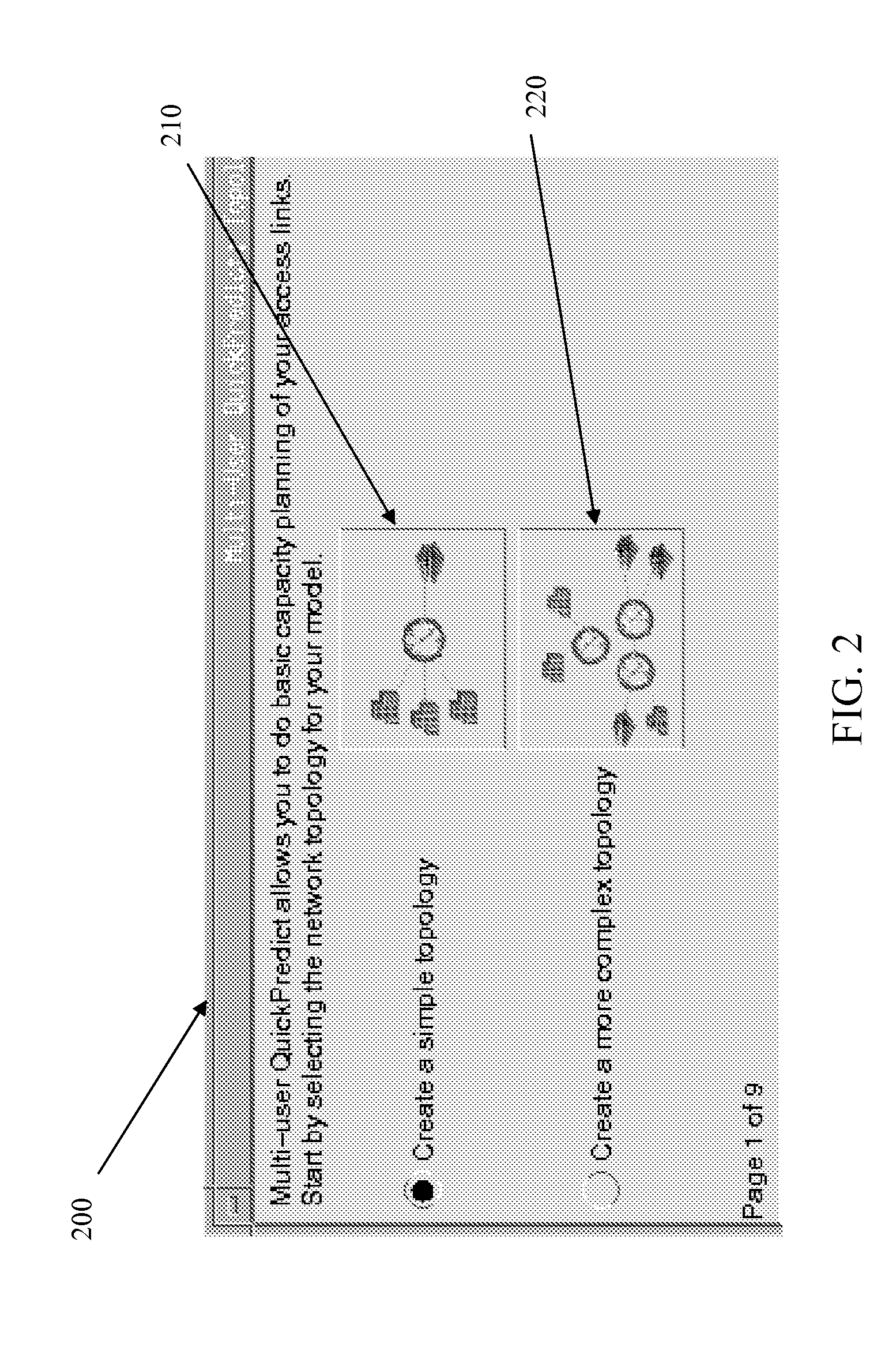
Data representing application deployment attributes, network topology, and network performance attributes based on a reduced set of element attributes is utilized to simulate application deployment. The data may be received from a user directly, a program that models a network topology or application behavior, and a wizard that implies the data based on an interview process. The simulation may be based on application deployment attributes including application traffic pattern, application message sizes, network topology, and network performance attributes. The element attributes may be determined from a lookup table of element operating characteristics that may contain element maximum and minimum boundary operating values utilized to interpolate other operating conditions. Application response time may be derived using an iterative analysis based on multiple instances of one or more applications wherein a predetermined number of iterations is used or until a substantially steady state of network performance is achieved.

Description

[0001]This application is a divisional of U.S. patent application Ser. No. 11 / 507,112, which claims the benefit of U.S. Provisional Patent Application No. 60 / 709,761, filed Aug. 19, 2005.BACKGROUND AND SUMMARY OF THE INVENTION[0002]The present system relates to the field of network capacity planning and particularly relates to a simplified system for determining an affect of application deployment on a network.[0003]A network is composed of a set of components, each with some associated behavior and properties. A simulation of such a network is a software program whose execution represents the network's components' properties and behavior.[0004]These simulations are often utilized to determine either an existing or planned network capacity. For example, the simulations may be utilized as a tool to determine how to resolve capacity issues in existing networks or as a tool to determine whether a planned network will have sufficient capacity. The elements of the simulation may be extra...

Claims


Application Information

Patent Timeline
Patent Type & Authority Applications(United States)
IPC IPC(8): G06F15/16
CPCH04L41/22H04L41/145
Inventor MALLOY, PATRICK J.ZNAMOVA, DANACOHEN, ALAIN J.DUNN, ANTOINESTROHM, JOHN W.HAIDER ALI, ABBASELSNER, RUSSELL MARK
Owner RIVERBED TECH LLC
Learn More