
Signal processing system and method for calibrating channel signals supplied from an array of sensors having different operating characteristics

a signal processing system and sensor technology, applied in the direction of receiving monitoring, transmission monitoring, instruments, etc., can solve the problems of microphone signals partially interfering with each other in a destructive manner, distortion of the output signal of the microphone,

Active Publication Date: 2011-11-01
NEC CORP
View PDF17 Cites 7 Cited by
  • Summary
  • Abstract
  • Description
  • Claims
  • Application Information

AI Technical Summary

Benefits of technology

[0009]It is therefore an object of the present invention to provide a calibration system and method for an array of sensors having different operating characteristics, which uses only input signals to perform calibration without advance calibration and additional computations and hardware.

Problems solved by technology

Since signals arriving in other directions have timing (phase) differences from the broadside signals, they interact with each other in a destructive manner.
However, if the operating characteristics of the microphones are not equal to each other due to their variation, the microphone signals partially interact with each other in a destructive way.
A similar problem occurs in the blocking matrix.
This results in the multi-channel canceller performing partial cancellation of the target signal and causes a distortion in its output signal.
This is disadvantageous for quantity production.
However, this prior art requires precision setting of the added noise level.
The amount of computations is substantial and the additive noise is a potential source of poor sound quality.
However, these prior art techniques require separate devices that present an increase in hardware.

Method used


Image

  • Signal processing system and method for calibrating channel signals supplied from an array of sensors having different operating characteristics
  • Signal processing system and method for calibrating channel signals supplied from an array of sensors having different operating characteristics
  • Signal processing system and method for calibrating channel signals supplied from an array of sensors having different operating characteristics

Examples


first embodiment

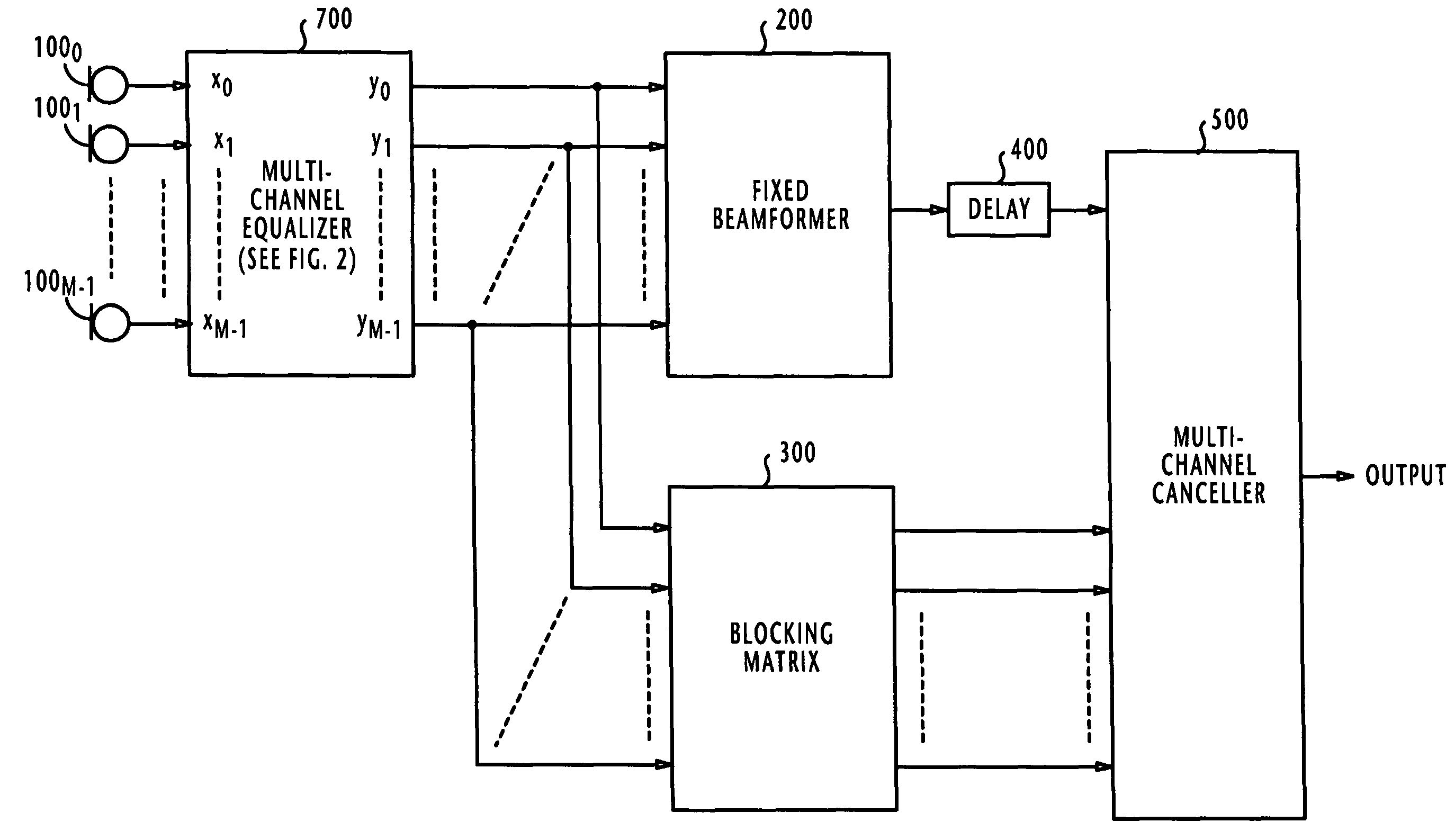
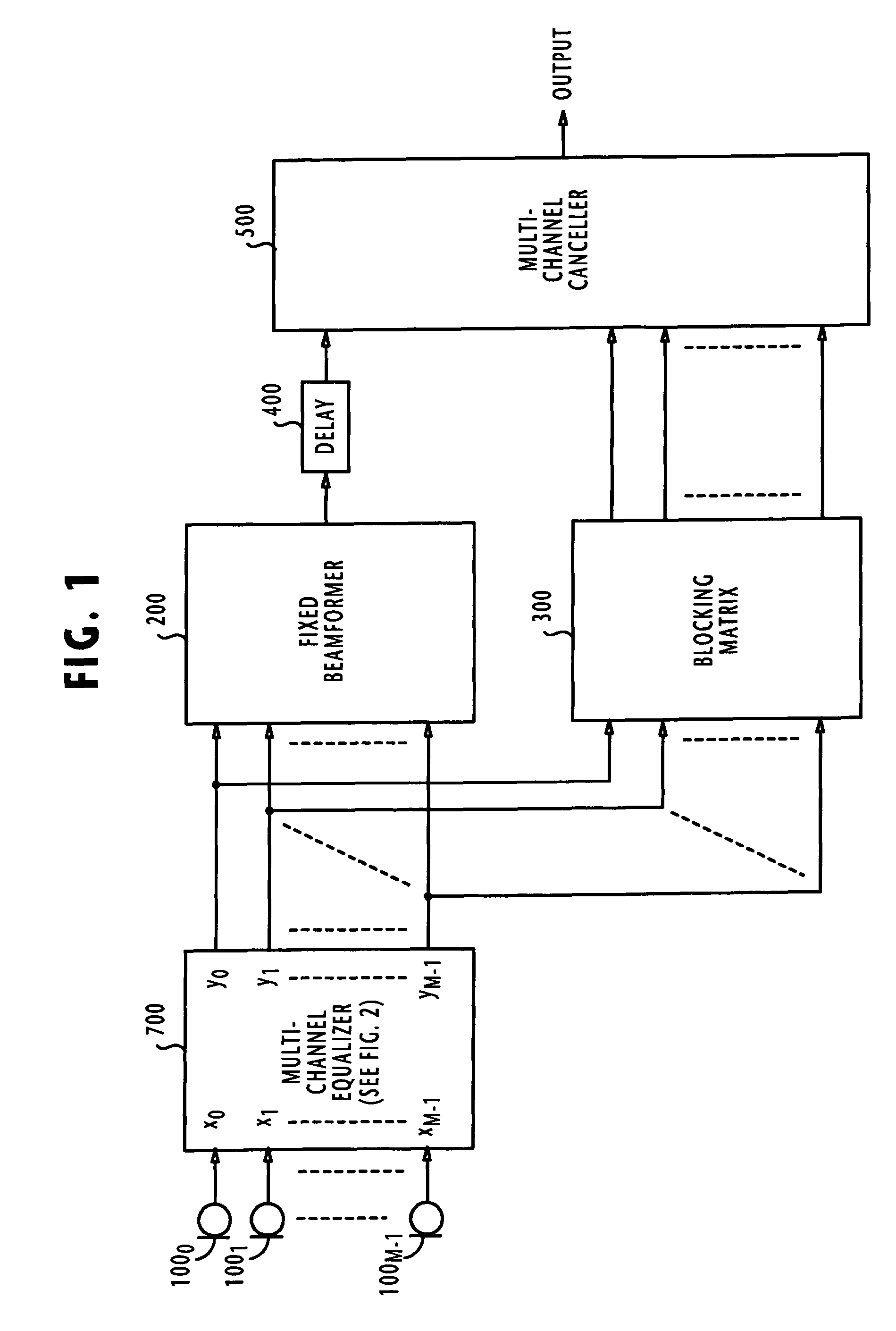
[0029]In FIG. 1, there is shown a signal processing system according to the present invention for an array of sensors that are equi-spaced at predetermined intervals along the surface of the array. For the purpose of disclosure, an array of microphones 1000˜100M-1 are used as sensors. A fixed beamformer 200, a blocking matrix 300 and a multi-channel canceller 500 are provided in the same manner as the corresponding elements of the Griffiths-Jim Beamformer described previously.

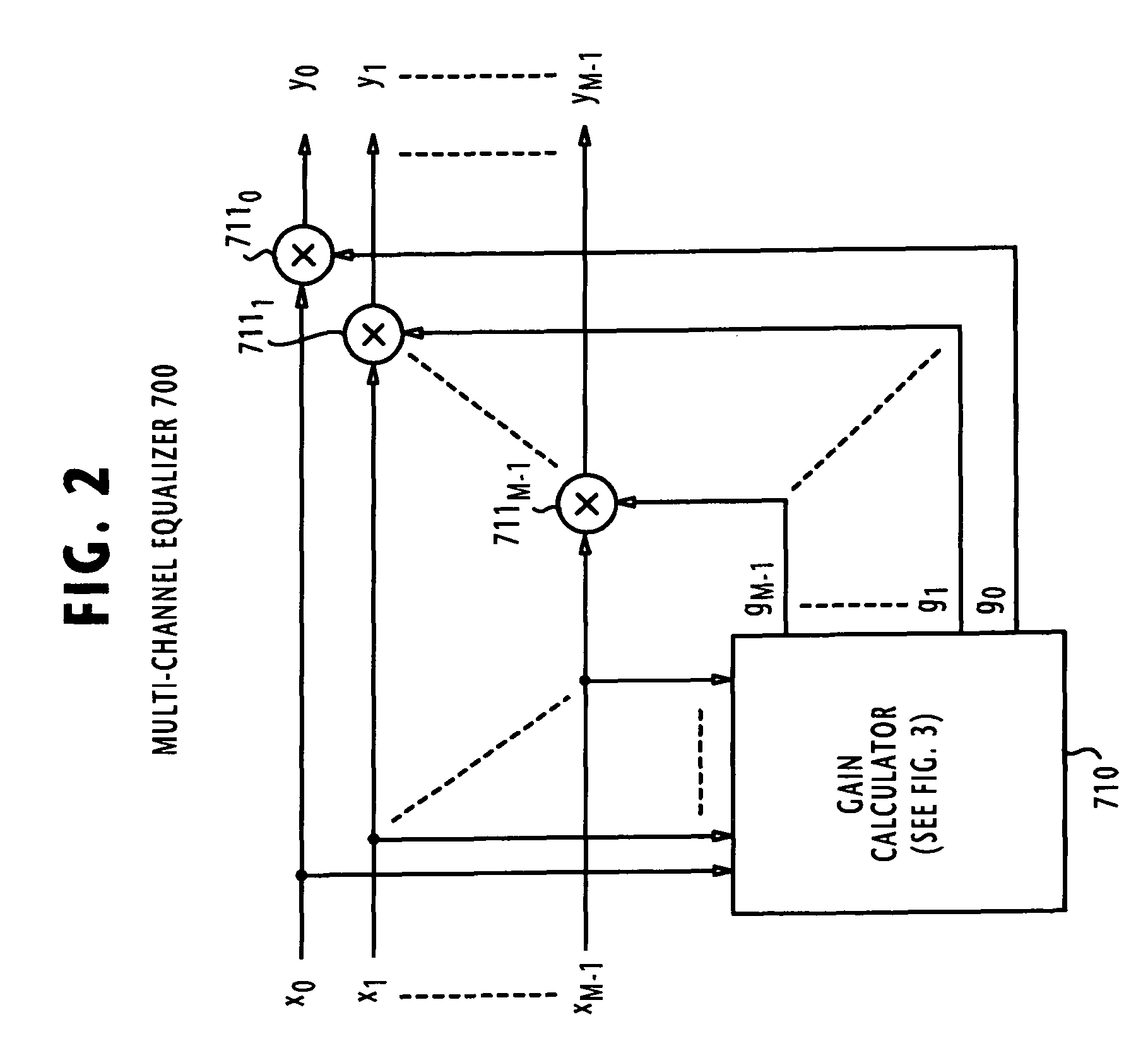
[0030]According to the present invention, a multi-channel equalizer 700 is provided to process microphone (or channel) signals from the array. Multi-channel equalizer 700 receives the input channel signals x0˜xM-1 from microphones 1000˜100M-1 and produces calibrated microphone signals y0˜yM-1 which are supplied to the fixed beamformer 200 and the blocking matrix 300.

[0031]In the beamformer, the calibrated microphone signals are linearly summed together to produce an enhanced target signal. The enhanced target s...

second embodiment

[0044]FIG. 4 is a block diagram of the present invention in which a subband multi-channel equalizer 800 is used instead of the multi-channel equalizer 700 of FIG. 1. In FIG. 4, parts corresponding to those of FIG. 1 bear the same numerals and the description thereof is omitted for simplicity.

[0045]As shown in detail in FIG. 5, the subband multi-channel equalizer 800-1 of FIG. 4 according to a first form of the present invention comprises M analysis filter banks 8100˜810M-1 which are respectively connected to the microphones 1000˜100M-1 to receive the channel signals x0˜xM-1. Each analysis filter bank 810i decomposes the frequency spectrum of the corresponding channel signal xi into N subband-channel signals xi,j (where i=0, 1, . . . , M-1, j=0, 1, . . . , N-1) representing the different frequency components, or subbands of the channel signal xi.

[0046]A plurality of multi-channel equalizers 7000˜700N-1 are provided corresponding in number to the N subband-channels decomposed by each ...


PUM


Abstract

In a signal processing system, a set of channel signals from an array of sensors of different operating characteristics are processed in calibration circuitry that calculates individual average values of the channel signals and calculates an average of the individual average values of channel signals as a reference value. Reciprocal calculators calculate reciprocal values of the individual average values of the channel signals. Scaling circuitry scales the reciprocal values by the reference value to produce a set of amplitude calibration signals and scales the channel signals by the calibration signals respectively. As a result, the channel signals are normalized by their own average values and scaled by the reference value to produce a set of calibrated channel signals.

Description

BACKGROUND OF THE INVENTION[0001]1. Field of the Invention[0002]The present invention relates to a signal processing system for calibrating multiple channel signals from an array of sensors, such as microphones and antennas, having different operating characteristics.[0003]2. Description of the Related Art[0004]It is well known to use an array of sensors, such as microphones and radio antennas equally spaced at predetermined intervals and oriented in a specified direction for cancelling interference signals by forming a beam in the direction of arrival of a target signal. When microphones are used as the array sensors, the Griffiths-Jim beamformer is the basic technique also known as a generalized sidelobe canceller. In the Griffiths-Jim beamformer as described in a literature “Microphone Arrays”, Springer, 2001, pages 87 to 109, signals from the microphone array are combined in a fixed beamformer to enhance a desired signal and attenuate interference signals. The array beam is form...

Claims


Application Information

Patent Timeline
Patent Type & Authority Patents(United States)
IPC IPC(8): H04B1/38G06E1/00H04R3/00G01R1/02
CPCH04R1/406H04R3/005H04B17/21H04R2201/403H04R2430/25H04R2201/401H04R1/20H04R3/00H04R5/02
Inventor SUGIYAMA, AKIHIKO
Owner NEC CORP
Learn More