Technique for controlling pumps in a hydraulic system

a hydraulic system and control technology, applied in the direction of fluid couplings, rotary clutches, servomotors, etc., can solve the problems of requiring maintenance and replacement, affecting the operation of the pump, and contributing to the parasitic loss of the pump

Inactive Publication Date: 2011-03-10
BUCYRUS INTERNATIONAL
View PDF100 Cites 44 Cited by
  • Summary
  • Abstract
  • Description
  • Claims
  • Application Information

AI Technical Summary

Benefits of technology

[0012]Another aspect of the present invention involves a hydraulic system that has a plurality of pumps which provide pressurized fluid to a plurality of hydraulic actuators. With this system, a usage value is produced for each pump indicating an amount that the respective pump has been used. For each of the plurality of hydraulic actuators, one of the pumps is assigned to each hydraulic actuator in response to the usage values for the plurality of pumps. The pumps with lower usage values are assigned to hydraulic actuators which work more, so as to equalize the use of each pump. The assignment of pumps to hydraulic actuators changes with changes in the usage values for the plurality of pumps. When a given one of the plurality of hydraulic actuators is to operate, hydraulic fluid is routed from the assigned pump to that hydraulic actuator.

Problems solved by technology

With those deactivation methods, however the pump still contributed to the parasitic losses as it was driven by the prime mover even when unloaded.
As a result, the pumps were exposed to different amounts of use and thus required maintenance and replacement at different intervals.

Method used


Image

  • Technique for controlling pumps in a hydraulic system
  • Technique for controlling pumps in a hydraulic system
  • Technique for controlling pumps in a hydraulic system

Examples


Embodiment Construction

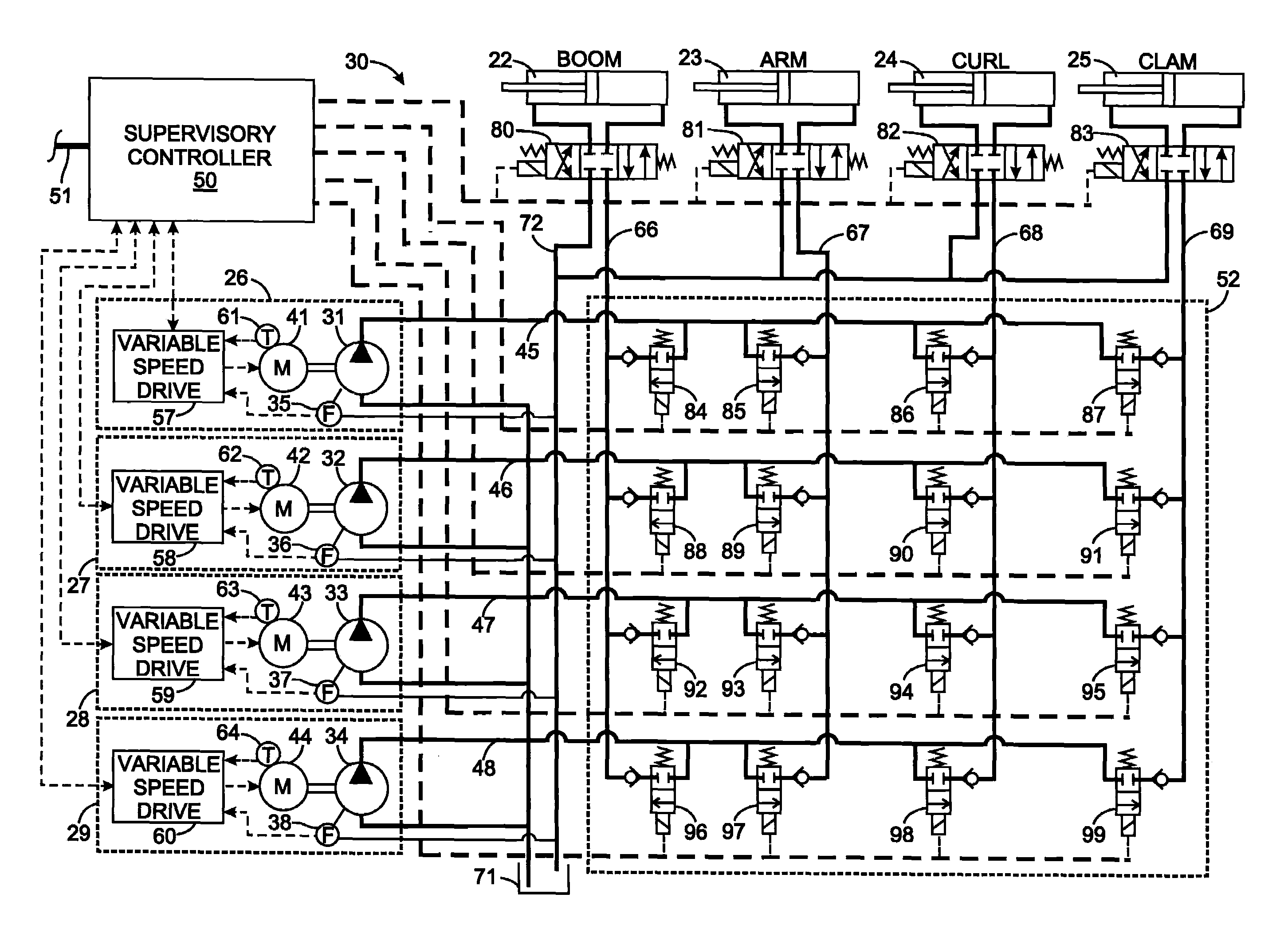
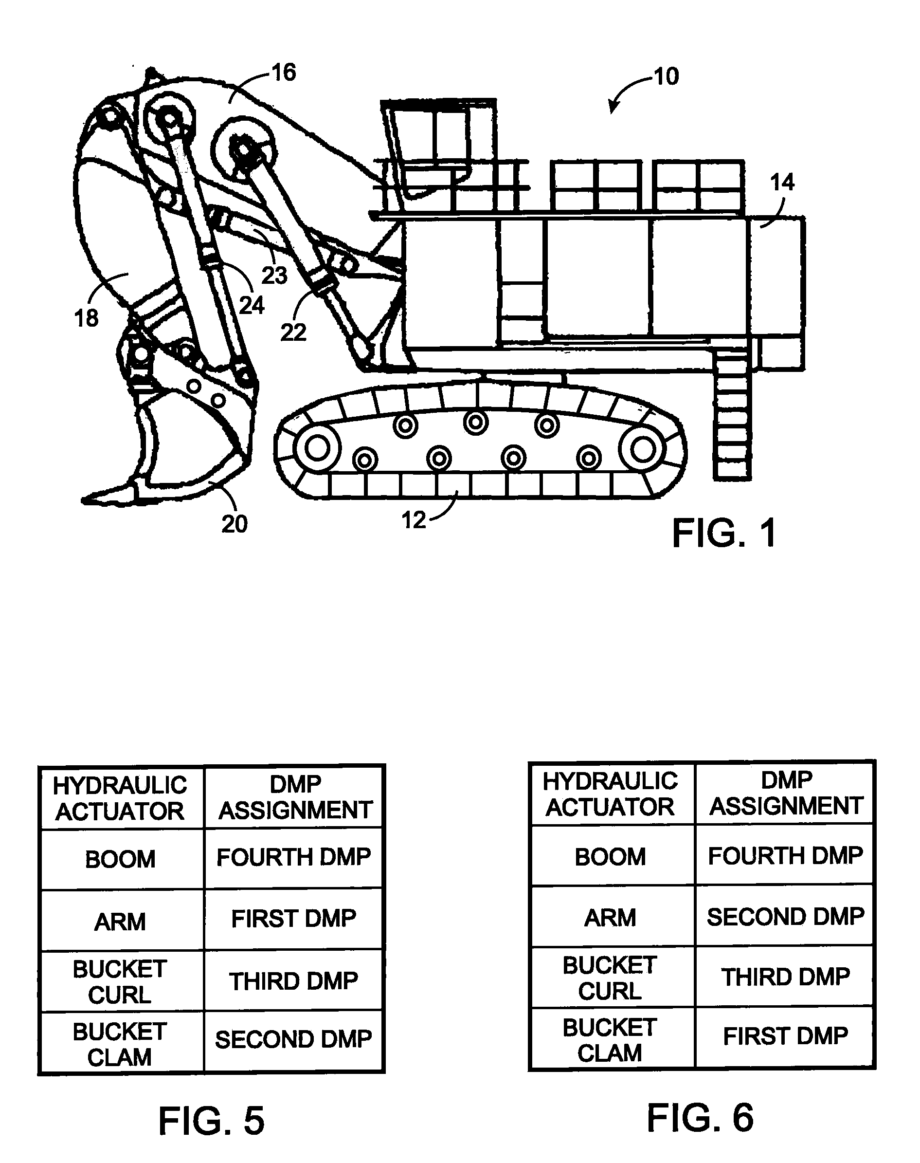
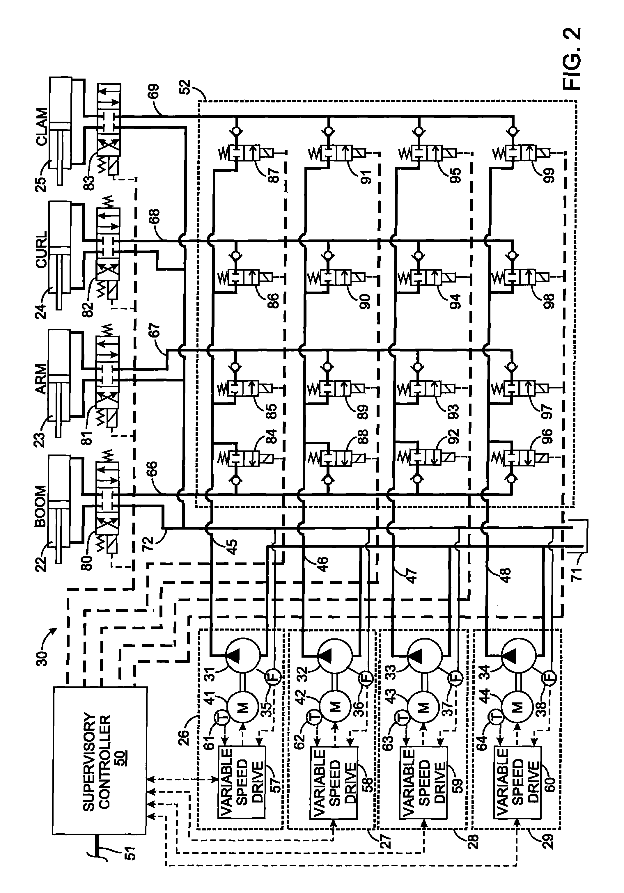
[0018]With initial reference to FIG. 1, an excavator, such as a front power shovel 10, has a crawler assembly 12 for moving the shovel across the ground. A cab 14 is pivotally mounted on the crawler tractor so as to swing in left and right. A boom 16 is pivotally mounted to the front of the cab 14 and can be raised and lowered by a boom hydraulic actuator 22 in the form of a first double-acting cylinder-piston assembly. An arm 18 is pivotally attached to the end of the boom 16 that is remote from the cab 14 and can be pivoted with respect to the boom by an arm hydraulic actuator 23 in the form of a second double-acting cylinder-piston assembly. At the remote end of the arm 18 from the boom is attached to a work tool, such as a bucket 20, that faces forward from the cab 14, hence this type of excavator is referred to as a front power shovel. The bucket 20 is pivoted or “curled” about the end of the arm 18 by a curl hydraulic actuator 24, in the form of a third double-acting cylinder-...


PUM


Abstract

A hydraulic system includes a plurality of pumps that provide pressurized fluid to a plurality of hydraulic actuators some of which work more that others. That system is controlled by producing a usage value for each of the plurality of pumps which indicates an amount that the respective pump has worked. One of the pumps is assigned to each hydraulic actuator in response to the usage values. The pumps with lower usage values are assigned to hydraulic actuators which work more, so as to equalize the use of each pump. The assignment of pumps to hydraulic actuators changes with changes in the usage values for the plurality of pumps. When a given one of the plurality of hydraulic actuators is to operate, hydraulic fluid is routed from the assigned pump to that given one of the plurality of hydraulic actuators.

Description

CROSS-REFERENCE TO RELATED APPLICATIONS [0001]Not ApplicableSTATEMENT REGARDING FEDERALLY SPONSORED RESEARCH OR DEVELOPMENT [0002]Not ApplicableBACKGROUND OF THE INVENTION [0003]1. Field of the Invention[0004]The present invention relates to hydraulic systems for excavators; and more particularly to controlling a plurality of pumps used in such hydraulic systems.[0005]2. Description of the Related Art[0006]Large excavators, such as power shovels, have a crawler truck on which the cab of the excavator is mounted. A boom is connected to the cab by a pivot joint that enables the boom to move up and down. The boom has a remote end to which one end of an arm is pivotally connected and a bucket is pivotally attached to the other end of the arm in turn has its own remote end to which. The bucket may be a clam-type having two pieces which open and close like a clam shell. The boom, the arm and the bucket are moved with respect to each other by separate hydraulic actuators in the form of cy...

Claims


Application Information

Patent Timeline
Patent Type & Authority Applications(United States)
IPC IPC(8): F15B11/08
CPCE02F9/2242F15B2211/857F15B19/005F15B2211/20515F15B2211/20538F15B2211/20576F15B2211/2658F15B2211/3059F15B2211/3111F15B2211/31576F15B2211/329F15B2211/6323F15B2211/633F15B2211/6343F15B2211/6651E02F9/2292
Inventor WEBER, ROBERTCHMIEL, WAYNE GEORGEPERUGINI, DAVE L.ONSAGER, MICHAEL GORDONHELFRICH, JOSEPH
Owner BUCYRUS INTERNATIONAL
Why Eureka
Try Eureka