Identification of air and/or fuel metering drift

a technology of air and/or fuel metering and drift detection, which is applied in the direction of electric control, instruments, machines/engines, etc., can solve the problem of not being able to determine whether

Active Publication Date: 2011-03-10
FORD GLOBAL TECH LLC
View PDF10 Cites 24 Cited by
  • Summary
  • Abstract
  • Description
  • Claims
  • Application Information

AI Technical Summary

Benefits of technology

[0008]To overcome at least one problem, a lambda sensor and a NOx sensor are used to allow detection of whether drift is occurring in fuel metering and / or air metering. In one embodiment, a first NOx value is estimated based at least on a measured mass air flow, a measured lambda, and an amount of burned gas in the intake gas. NOx is also measured. A first delta NOx based on a difference between the first NOx value and the measured NOx is determined. A first delta NOx value is compared to a first threshold and a drift in a mass fuel flow measurement is inferred when the first delta value is less than the first threshold. If such a drift in mass fuel flow, calibration coefficients associated with the mass fuel flow measured are corrected. In some embodiments, the first NOx value is further based on engine operating conditions. In some embodiments, the first delta NOx is based on the difference between the first NOx value and the measured NOx squared integrated over a predetermined period of time.
[0009]A second NOx value is based at least on a measured mass fuel flow, the measured lambda, and the amount of burned gas in the intake gas, a second delta NOx based on a difference between the second NOx value and the measured NOx is determined. A second delta NOx value is compared to a second threshold; and a drift in a mass air flow measurement is inferred when the second delta value is less than a second threshold. Calibration coefficients associated with the mass air flow measurement are corrected when the drift in mass fuel flow is inferred.

Problems solved by technology

In background systems, it is not possible to determine whether the drift is to be attributed primarily to the parameter “air” or to the path of the MAF sensor or to the parameter “injected fuel” for example on account of a blocked injector or injector system or on account of wear of the injector or of the injector system.

Method used


Image

  • Identification of air and/or fuel metering drift
  • Identification of air and/or fuel metering drift
  • Identification of air and/or fuel metering drift

Examples


Embodiment Construction

[0012]As those of ordinary skill in the art will understand, various features of the embodiments illustrated and described with reference to any one of the Figures may be combined with features illustrated in one or more other Figures to produce alternative embodiments that are not explicitly illustrated or described. The combinations of features illustrated provide representative embodiments for typical applications. However, various combinations and modifications of the features consistent with the teachings of the present disclosure may be desired for particular applications or implementations.

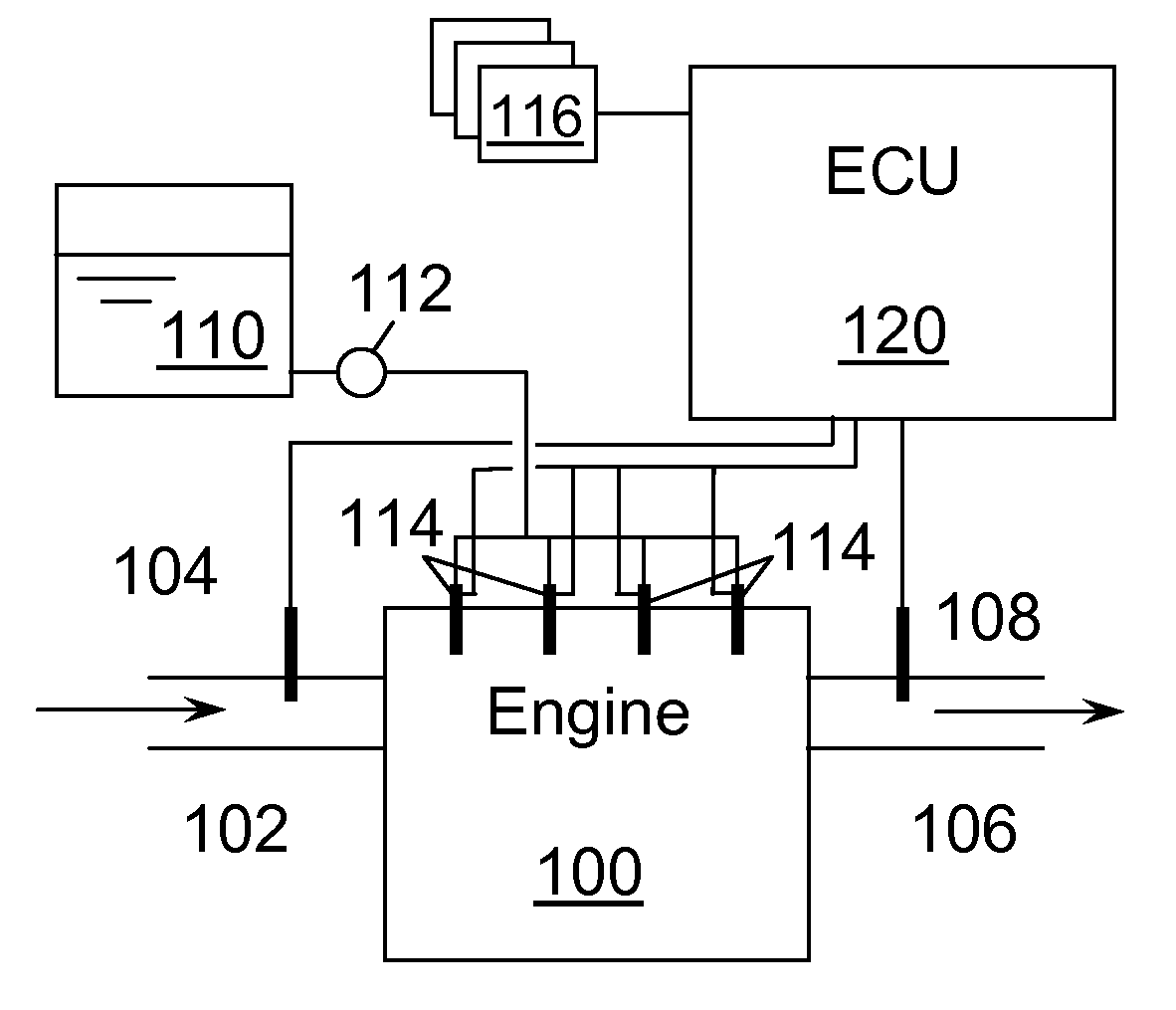
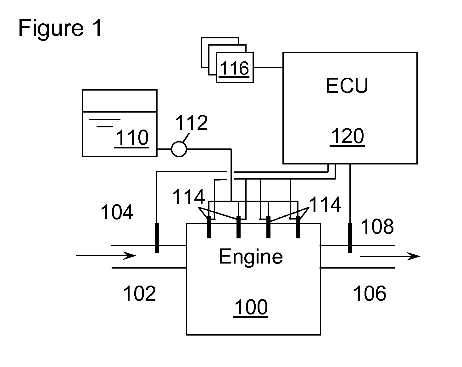
[0013]FIG. 1 shows an engine 100 having an intake 102 with a mass air flow (MAF) sensor 104 disposed in intake 102. Alternatively, mass air flow can be determined by other combinations of sensors, such as can determine engine speed and intake density. Engine 100 has an exhaust 106 with a sensor 108 or sensors. Sensor 108 may be an exhaust oxygen sensor (lambda sensor) based on which stoichi...


PUM


Abstract

The disclosure relates to a system and method for identifying whether a difference between measured lambda and computed lambda, based on mass air flow and mass fuel flow, is due to a drift in fuel metering or a drift in air metering. The determination is based on also measuring exhaust gas NOx using a NOx sensor. By comparing the measured NOx to modeled NOx, drift can be attributed appropriately to the air flow measurement and/or the fuel flow measurement. Appropriate correction in the calibration can be undertaken to overcome sensor drift and/or drift in the fuel injector/fuel system flow characteristics.

Description

CROSS-REFERENCE TO RELATED APPLICATIONS[0001]This application claims foreign priority benefits under 35 U.S.C. § 119(a)-(d) to DE 10 2009 029 257.8, filed Sep. 8, 2009, which is hereby incorporated by reference it its entirety.BACKGROUND[0002]1. Technical Field[0003]The disclosure relates to a method for identifying and correcting drift of fuel and / or air quantity metering in an internal combustion engine.[0004]2. Background Art[0005]Measuring an exhaust-gas lambda value is one possibility for identifying a drift in the fuel metering or in the air quantity metering. This may be achieved by virtue of an estimated lambda value being calculated on the basis of a measured mass air flow and the original set value of the fuel quantity. The measured mass air flow may be determined by an mass air flow sensor, a so-called MAF sensor.[0006]The drift of the MAF sensor with progressive service life may amount to up to + / −5%. The drift of the fuel injection quantity with progressive service life...

Claims


Application Information

Patent Timeline
Patent Type & Authority Applications(United States)
IPC IPC(8): G01F25/00G01M15/04
CPCF02D41/1454F02D41/1461F02D41/1462Y02T10/40F02D41/22F02D2200/0616F02D41/18
Inventor YACOUB, YASSER MOHAMED SAYED
Owner FORD GLOBAL TECH LLC
Why Eureka
Try Eureka