Shell-and-Tube Heat Exchanger

a heat exchanger and shell technology, applied in the direction of tubular elements, lighting and heating apparatus, stationary conduit assemblies, etc., can solve the problem of not being able to remove any more, and achieve the effect of efficient cleaning and efficient cleaning

Inactive Publication Date: 2011-03-10
KRONES AG
View PDF14 Cites 15 Cited by
  • Summary
  • Abstract
  • Description
  • Claims
  • Application Information

AI Technical Summary

Benefits of technology

[0006]The deliberate turning away from a fold B:T ratio that is usually standard for an optimum heat expansion compensation and the adoption of a ratio of B:T of about 1 or more, which is less advantageous for compensation, at least on the surface of the fold that can be contacted by the product, makes it possible that the surface that can be contacted by the product can be cleaned for achieving a hygienically irreproachable state of the product because there are relatively moderate directional changes in the rounded folds and relatively weakly curved surfaces and there are no critical dead spaces. Hence, the product is less prone to sticking, but is always swiftly flushed out of the fold. Cleaning media can efficiently eliminate product residues and the media themselves can be flushed out easily and / or removed without any residues. To accomplish the compensatory action required on the whole, one need only provide a corresponding additional number of folds. This, however, is certainly acceptable with respect to the achievable, hygienically irreproachable conditions for the product / product flow guidance and hermetic tightness in the shell-and-tube heat exchanger. Due to the accepted deterioration of the compensatory action of each fold, which contacts the product e.g. with its inside and is provided as such for the technical purpose of compensating heat expansions, it is only now that the bellows is given the hygienic qualification for the product / product flow guidance in the shell-and-tube heat exchanger, also for the reason that a harmonious surface extension achieves very advantageous flow conditions that drastically improve the cleaning efficiency in particular. Hence, a shell-and-tube heat exchanger with hygienic bellows is accomplished.
[0010]In another embodiment, the inner diameter of the bellows has a size which lies between approximately the inner diameter of the inner or casing tube comprising the bellows and said inner diameter less the depth of the folds. Depending on the specific application of the bellows in the casing tube or in an inner tube, undesired constrictions within said bellows / inner diameter region can be avoided or minimized in the respective flow channels.
[0011]In one embodiment the bellows comprises substantially circular cylindrical tube sockets welded to the inner or casing tube, which are inserted in or over section ends of the inner or casing tube. Integrating the bellows into the respective tube can be easily mastered by way of production technology. The welds are tight and can withstand high pressure differences without any problems. The bellows can be arranged at the respectively optimum position of the tube.
[0013]In an expedient embodiment a casing tube forms a shell-and-tube heat exchanger module with a plurality of inner tubes. The bellows, at least one bellows, can be arranged approximately in the longitudinal center of the heat-exchanger module so as to develop its compensatory action in an optimum way. Preferably, the bellows is positioned in the casing tube in such a way that the surface of the bellows which can be contacted by the product is oriented towards the inner tubes which are accommodated in the casing tube and may be smooth.
[0014]It is important for an efficient cleaning when at least on the surface which can be contacted by the product the fold has such a harmonious surface extension that essentially turbulent flow conditions are promoted there, such flow conditions completely encompassing all recesses of the bellows. Essentially turbulent flow conditions offer the advantage that no zones are formed where it must be feared that not only the product will deposit, but a cleaning medium is also not in a position to develop an efficient cleaning action.

Problems solved by technology

The heat-expansion compensating device is here a slide connection with seals or a floating or moveable bearing permitting thermally caused relative movements, but creating dead spaces in which the product can settle in such a way that despite intensive cleaning it cannot be removed any more, or requires a dismantling operation for hygienically irreproachable cleaning.

Method used


Image

  • Shell-and-Tube Heat Exchanger
  • Shell-and-Tube Heat Exchanger
  • Shell-and-Tube Heat Exchanger

Examples


Embodiment Construction

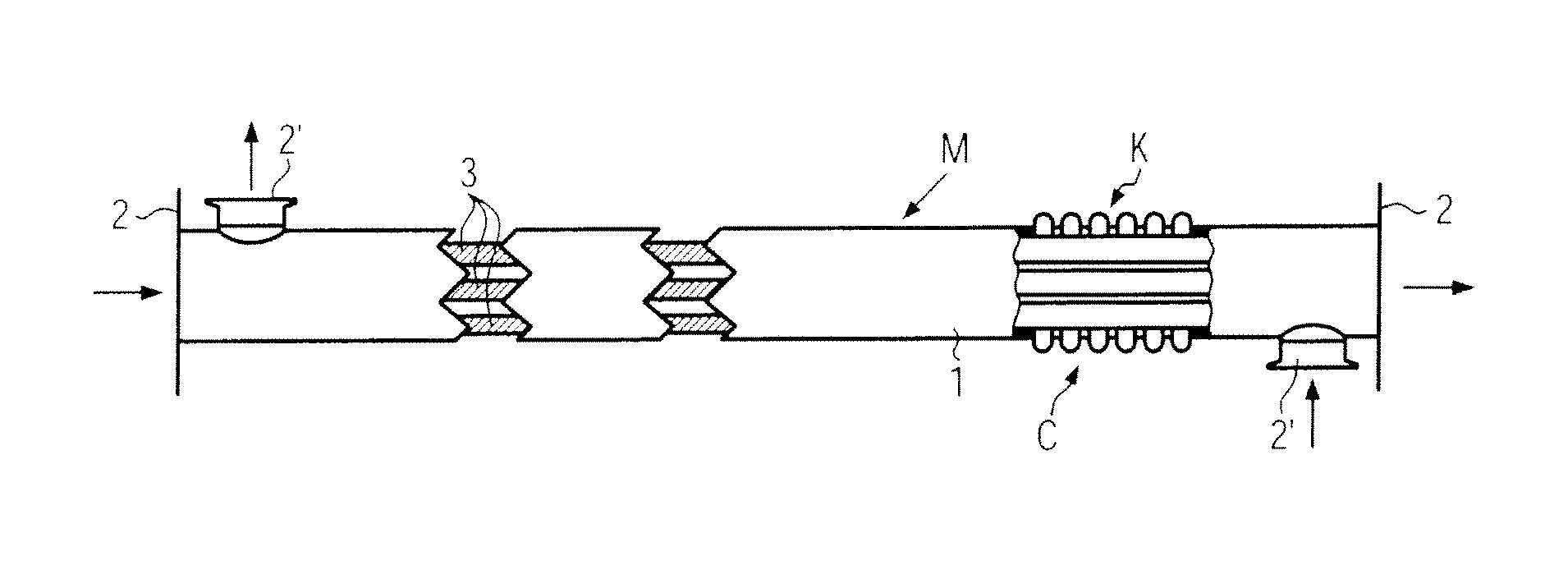
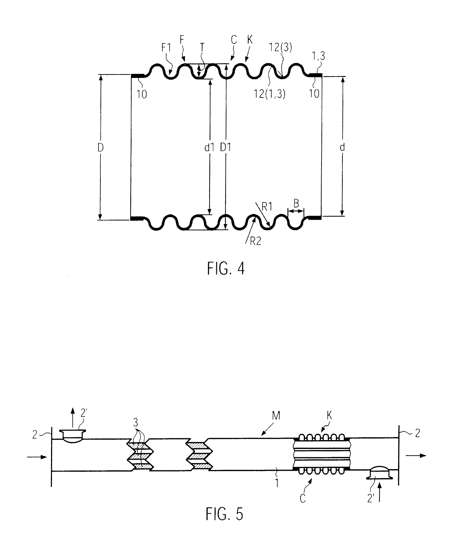
[0022]Each of FIGS. 1 and 5 illustrates an individual module M of a shell-and-tube heat exchanger W shown in broken line, as is e.g. used in the bottling or filling industry for liquid food products (e.g. water, juices, milk) for a product / product flow guidance in the heat treatment (heating or cooling) of a food product. In the shell-and-tube heat exchanger W it is possible to install a plurality of modules so as to obtain flow paths for the product that are as long as possible. Module M may here have a length of e.g. 3.0 m, 6.0 m, or even more.

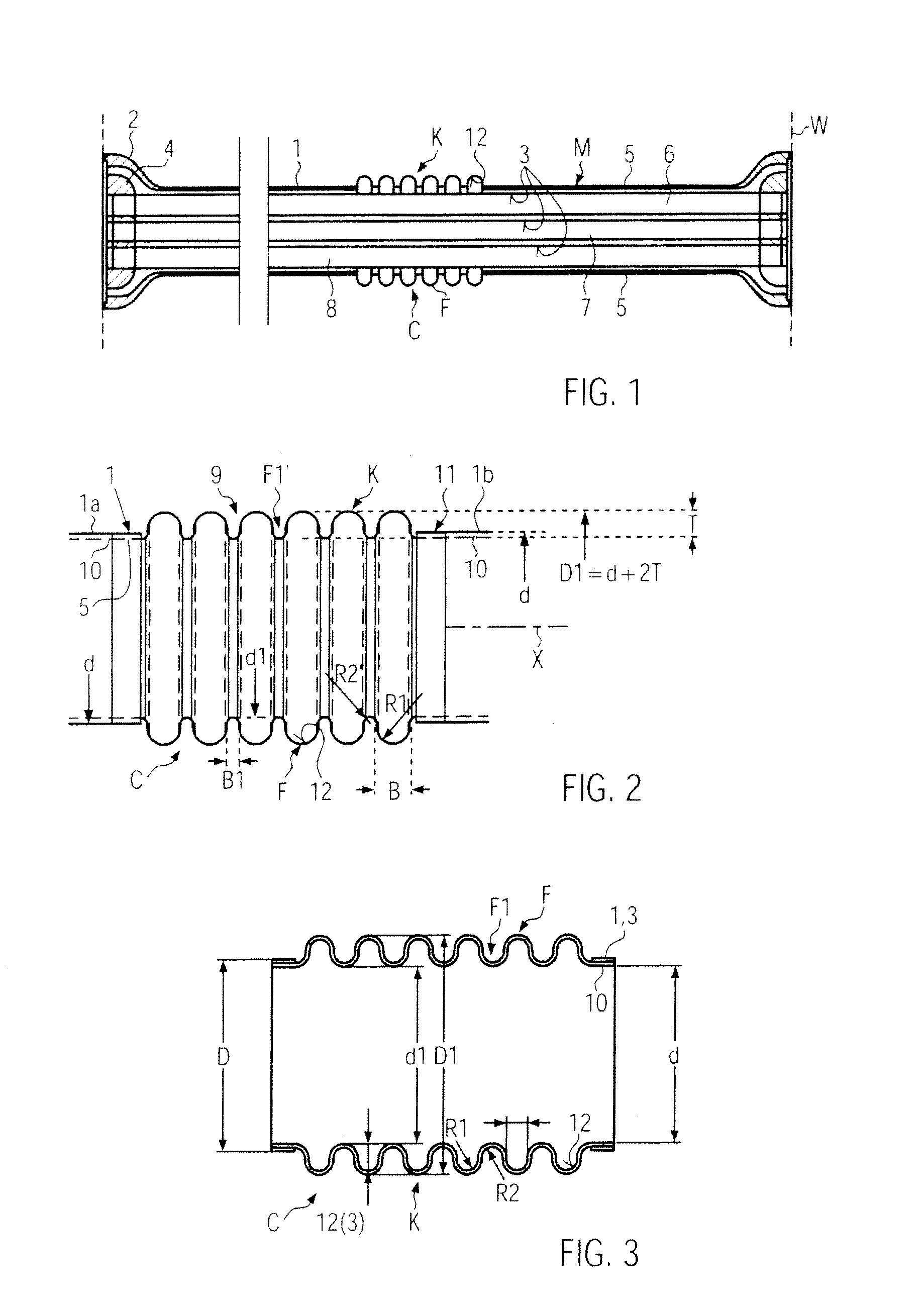
[0023]In FIG. 1 the module M comprises a casing tube 1, e.g. of stainless steel, which comprises end-sided fastening flanges 2 for installation in the shell-and-tube heat exchanger W. In the casing tube 1 at least one inner tube 3 is provided that extends substantially axially parallel with respect to the casing tube 1 between fastening flanges 4. In the embodiment in FIG. 1, several inner tubes 3 are provided that are combined to form a tub...


PUM


Abstract

A shell-and-tube heat exchanger including a casing tube and at least one inner tube for treating liquid food products, optionally also with a product / product flow guidance, and having at least one thermal-expansion compensating device for the casing and / or inner tube, with the compensating device having a surface which can be contacted by the product to be treated, where the surface is provided on a bellows integrated into the casing and / or inner tube, with a plurality of relatively wide folds which extend around the tube axis and are of rounded cross-section, with the respective fold being configured with a radial depth and an axial width with a ratio of B:T of about 1 or more and to be cleanable on the product side in a hygienically irreproachable way.

Description

CROSS-REFERENCE TO RELATED APPLICATION[0001]The present application claims the benefit of priority of German Application No. 102009040560.7, filed Sep. 8, 2009. The entire text of the priority application is incorporated herein by reference in its entirety.FIELD OF THE DISCLOSURE[0002]The present disclosure relates to a shell-and-tube heat exchanger of the type used for treating liquid foods.BACKGROUND[0003]Shell-and-tube heat exchangers e.g. for product / product flow guidance are known from DE 600 19 635 T2 and DE 102 56 232 B4. The heat-expansion compensating device is here a slide connection with seals or a floating or moveable bearing permitting thermally caused relative movements, but creating dead spaces in which the product can settle in such a way that despite intensive cleaning it cannot be removed any more, or requires a dismantling operation for hygienically irreproachable cleaning. Under hygienic aspects such compensating devices are not recommended by the authorities in ...

Claims


Application Information

Patent Timeline
Patent Type & Authority Applications(United States)
IPC IPC(8): F28D1/053F28F7/00
CPCF28D7/10F28D7/16F28F2265/26F28F1/08F28D2021/0042
Inventor ZACHARIAS, JORG
Owner KRONES AG
Why Eureka
Try Eureka