Sensor Device and Information Processing Device

a technology of information processing device and sensor device, which is applied in the field of sensor device and information processing device, can solve problems such as and achieve the effect of preventing the change of capacitance and preventing the failure of information processing devi

Active Publication Date: 2011-03-10
SONY CORP
View PDF9 Cites 28 Cited by
  • Summary
  • Abstract
  • Description
  • Claims
  • Application Information

AI Technical Summary

Benefits of technology

[0017]According to another embodiment of the present invention, there is provided an information processing device including a pressure-sensitive sensor which changes shape in response to pressing of an operation tool and which detects change in capacitance due to the change in shape, a barrier which covers at least a part of the pressure-sensitive sensor and which prevents change in capacitance of the pressure-sensitive sensor due to capacitive coupling that occurs with approach between the p

Problems solved by technology

As a result, in the case of detecting input operation by a user's finger or the like and performing processing according thereto by using the touch panel and the press

Method used


Image

  • Sensor Device and Information Processing Device
  • Sensor Device and Information Processing Device
  • Sensor Device and Information Processing Device

Examples


first embodiment

3. First Embodiment

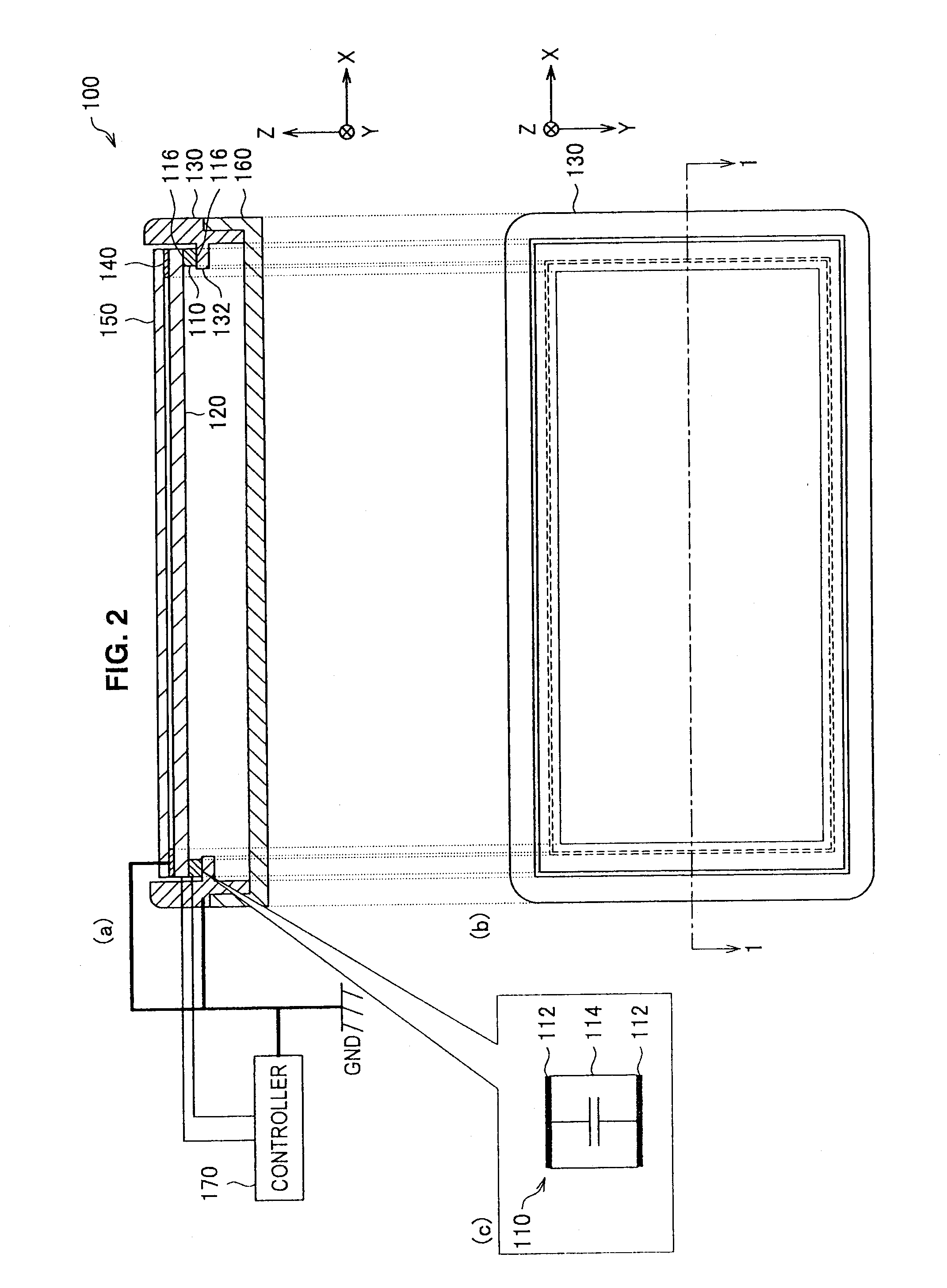
[0050]Subsequently, a sensor device according to a first embodiment of the present invention will be described in detail with reference to FIG. 2 to FIG. 3. FIG. 2 are a sectional view and a plan view for explaining the sensor device according to the first embodiment of the present invention. FIG. 3 are sectional views of the sensor device according to the embodiment to which fingers are in proximity. The sensor device is provided to a mobile device, for example.

[0051]First, a configuration of the sensor device 100 will be described with reference to FIG. 2. FIG. 2 (a) is a sectional view showing a cross-section of the sensor device 100 taken along the cross-section line 1-1 in FIG. 2 (b). Moreover, FIG. 2 (b) is a plan view of the surface of the sensor device 100 seen from the positive Z-axis direction. Moreover, FIG. 2 (c) is an enlarged sectional view of the pressure-sensitive sensor 110 in FIG. 2 (a). As shown in FIG. 2 (a), the sensor device 100 includes a ba...

second embodiment

4. Second Embodiment

[0074]Subsequently, a sensor device 200 according to a second embodiment of the present invention will be described with reference to FIG. 5. FIG. 5 is a sectional view of the sensor device 200. The sensor device 200 includes a base member 160, a pressure-sensitive sensor 210, a touch panel 220, a top plate 250, and a conductive housing 230. Moreover, the pressure-sensitive sensor 210 includes two electrodes and an elastic body.

[0075]As shown in FIG. 5, the base member 160 and a controller 170 have substantially the same configurations as those of the base member 160 and the controller 170 according to the first embodiment. Moreover, also regarding the top plate 250, the top plate 250 is formed smaller than the touch panel 220 in the XZ direction due to the structures of the conductive housing 230 and the pressure-sensitive sensor 210, but the other aspects of the configuration are substantially the same as those of the top plate 150 according to the first embodi...

third embodiment

5. Third Embodiment

[0082]Subsequently, a sensor device 300 according to a third embodiment of the present invention will be described with reference to FIG. 6. FIG. 6 is a sectional view for explaining the sensor device 300. The sensor device 300 includes a base member 360, pressure-sensitive sensors 310, a touch panel 120, a top plate 150, and conductive rubbers 330. Moreover, the pressure-sensitive sensor 310 includes two electrodes 312 and an elastic body 314.

[0083]As shown in FIG. 6, configurations of the touch panel 120 and the top plate 150 are the same as those of the touch panel 120 and the top plate 150 according to the first embodiment. Moreover, also regarding the base member 360, although the form of the base member 360 is different from that of the base member 160 according to the first embodiment due to the relationship with other components, the other aspects of the configuration are substantially the same. Therefore, in the third embodiment of the present invention, ...


PUM


Abstract

A sensor device is provided which includes a pressure-sensitive sensor which changes shape in response to pressing of an operation tool and which detects change in capacitance due to the change in shape, and a barrier which covers at least a part of the pressure-sensitive sensor and which prevents change in capacitance of the pressure-sensitive sensor due to capacitive coupling that occurs with approach between the pressure-sensitive sensor and the operation tool.

Description

BACKGROUND OF THE INVENTION[0001]1. Field of the Invention[0002]The present invention relates to a sensor device and an information processing device.[0003]2. Description of the Related Art[0004]In recent years, a variety of information processing devices such as mobile phones and car navigation systems each of which includes a sensor device including a touch panel have been distributed in the market. For operation of the touch panel, a variety of methods such as a resistive method, an electromagnetic method, and a capacitive method are adopted. According to such technology, by the contact of an operation tool such as a finger or a touch pen on the touch panel, the position of the operation tool can be detected.[0005]Since the touch panel described above is for detecting the position of an operation tool, the pressure on the touch panel is difficult to be determined, which thus limits realizable operation. On the other hand, there have been also developed information processing devi...

Claims


Application Information

Patent Timeline
IPC IPC(8): G06F3/045
CPCG06F3/0414G06F3/044H03K2217/960765H01G5/16G06F2203/04105G06F2203/04107G06F3/0445G06F3/0447G06F3/017G06F3/03545
Inventor YAMANO, IKUO
Owner SONY CORP
Why Eureka
Try Eureka