Light Emitting Diode Tube

Inactive Publication Date: 2011-03-10
THERMOSHUTTLE CO LTD
View PDF3 Cites 55 Cited by
  • Summary
  • Abstract
  • Description
  • Claims
  • Application Information

AI Technical Summary

Benefits of technology

The present invention discloses a LED light tube along with the heat dissipation fins on it and built as one piece. The heat dissipation fins are shaped like bats with wings extended out to have a well-defined center line, which helps create a

Problems solved by technology

These conventional lamps, in general, consume more energy and expect shorter service life than LED lamps do.
But until recently, the luminosity of LEDs has been pretty limited, thus confining their use to such devices as signal lights, tail lights of vehicles, decorative lights, etc., which requires relatively low brightness.
They consume less energy and, with adequate heat dissipation, enjoy longer service life, even lasting tens of thousands of hours.
After being

Method used


Image

  • Light Emitting Diode Tube
  • Light Emitting Diode Tube
  • Light Emitting Diode Tube

Examples


Embodiment Construction

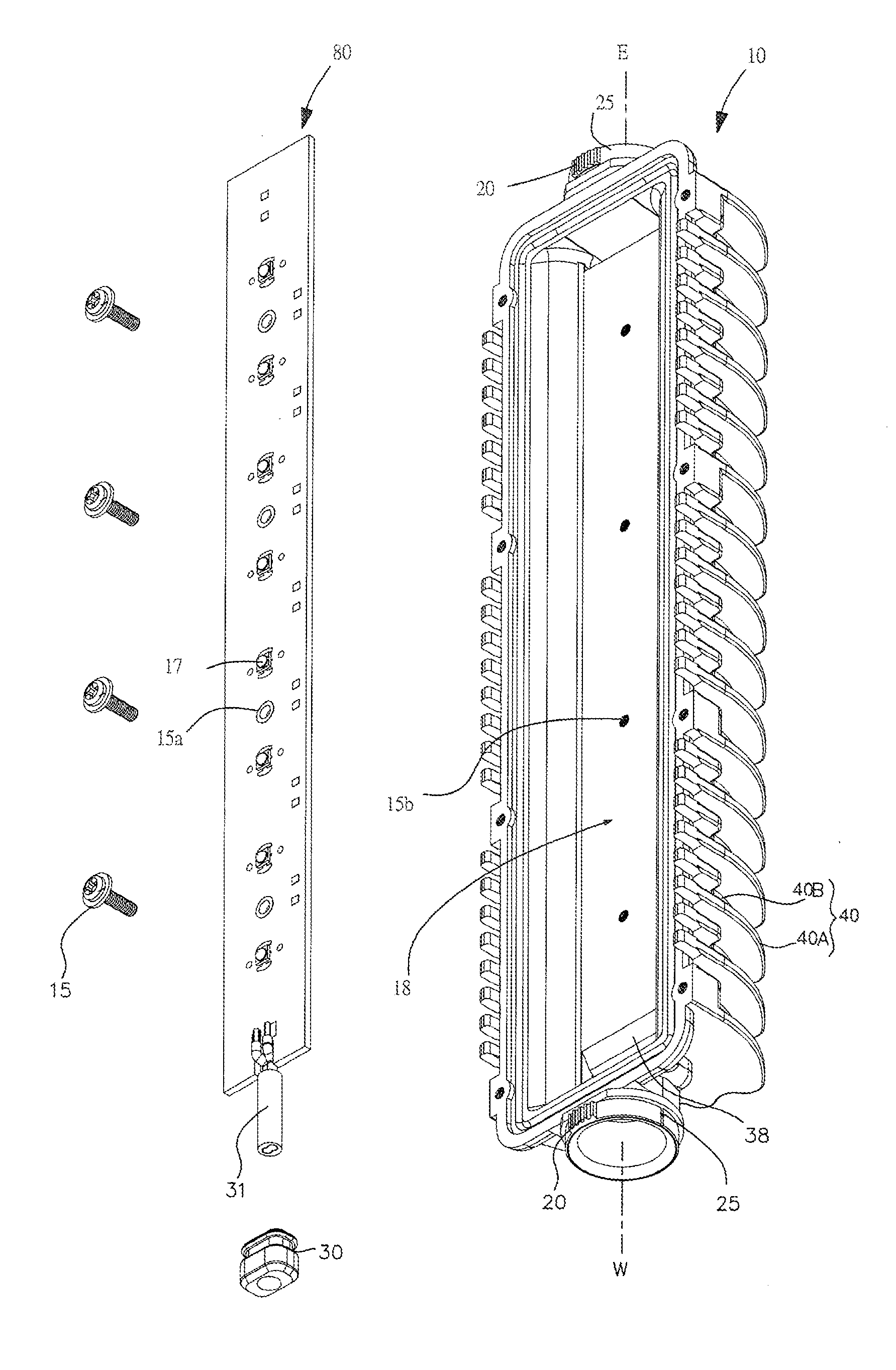
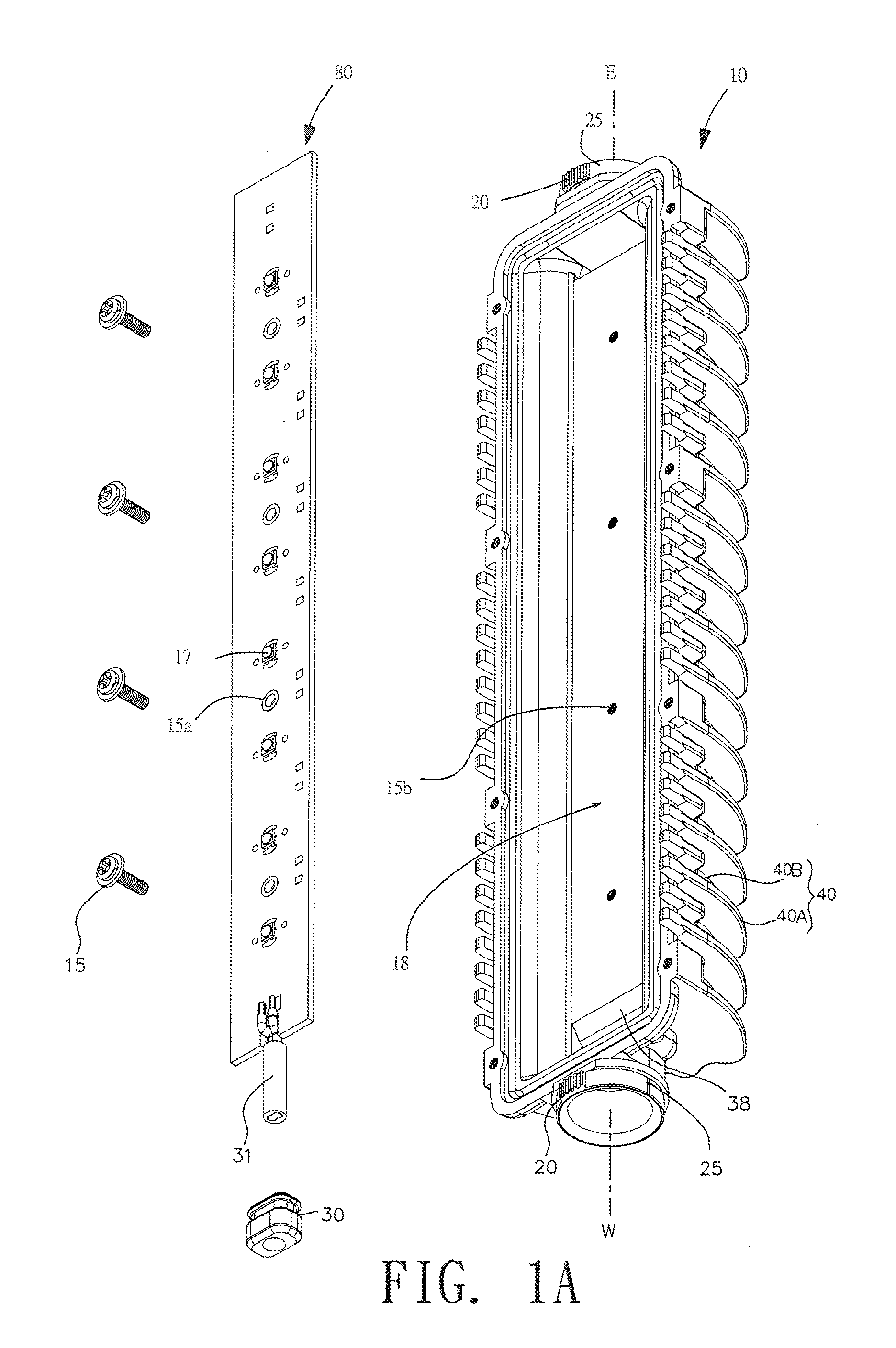
The following description will be illustrated with drawings. In the embodiment, the exemplary example is for illustrating convenience only not to limit the claim scope. For example, the permutation disposed of the LED chips on the LED PC board is not limited to the one illustrated in the drawing. It can be multiple chips in one row or multiple chips in multiple rows as any person skilled in the art can do. In one of the preferred embodiments, the LED chips are arranged at most in two rows, so that each LED chip in the tube can get better heat dissipation.

FIG. 1A shows the explosive view of the LED light tube hull 10 and the LED circuit board as disclosed by the present invention. The tube hull has a semi-cylindrical arch on the back of the light tube's hull 10. The back of the LED PC board is a metal plate in touch with the surface of the recessed platform 18. The metal plate is designed to simplify the process of mounting the LED PC board 80 onto the light tube hull 10. The LED PC ...


PUM


Abstract

A LED light tube is disclosed. The light tube, along with the heat dissipation fins on it, is built as one piece. The heat dissipation fins are shaped like bats with wings extended out to have a well-defined center line, which helps create a better heat convection condition in the tube. The light tube also formed with two extended axis having a plurality of teeth formed thereon so as to provide the light tube having capability of angle adjustment about the axis of the light tube.

Description

BACKGROUND OF THE INVENTION1. Field of the InventionThe present invention relates to a LED tube, particularly one designed to be used in / on street lamps or outdoor lighting devices.2. Description of the Prior ArtConventional street lamps are mostly either halogen or mercury lamps attached on the bent end of a lamppost. The lamp unit usually contains one or more than one halogen lamp or light emitting component, along with a reflector shield to add extra light to achieve desired illumination.These conventional lamps, in general, consume more energy and expect shorter service life than LED lamps do.LEDs are known to have more concentrated beams than do conventional light sources. But until recently, the luminosity of LEDs has been pretty limited, thus confining their use to such devices as signal lights, tail lights of vehicles, decorative lights, etc., which requires relatively low brightness. However, as a result of the invention of white LEDs and the dropping of manufacturing cost ...

Claims


Application Information

Patent Timeline
IPC IPC(8): F21V29/00
CPCF21V14/02F21V29/004F21V29/767F21Y2101/02F21Y2103/003F21W2131/103F21Y2103/10F21Y2115/10F21V29/76
Inventor SHIAU, FUH-YUARNWU, CHIN-CHUN
Owner THERMOSHUTTLE CO LTD
Why Eureka
Try Eureka