Device for detecting and signaling a physical value when connected to a rim, and rim comprising such a device

a technology for detecting and signaling a physical value, which is applied in the direction of vehicle tyre testing, instruments, roads, etc., can solve the problems of not being able to visually check if the sensor is still fastened correctly, screwing a wheel sensor to the tire valve, and being more expensiv

Active Publication Date: 2007-08-14
HUF BAOLONG ELECTRONICS BRETTEN GMBH
View PDF7 Cites 34 Cited by
  • Summary
  • Abstract
  • Description
  • Claims
  • Application Information

AI Technical Summary

Benefits of technology

[0017]Suited as proximity sensors for the purposes of the invention are, above all, capacitive and inductive sensors. A capacitive proximity sensor can be formed by designing and arranging a first capacitor electrode in the wheel sensor in such a way that in the predetermined mounting position of the wheel sensor it will come to lie closely opposite the rim surface so that the rim acts as a second capacitor electrode which, together with the first capacitor electrode, forms a capacitor whose capacitance would vary strongly if the wheel sensor should drop off the rim. An especially favorable solution is obtained if the proximity sensor comprises two capacitors each of them having a first electrode in the wheel sensor and both of them using the rim as a common coupling electrode. This embodiment provides the advantage that well-defined electric potentials are encountered on the electrodes of the proximity sensor capacitors even without any direct electric connection between the wheel sensor and the rim.
[0018]If the proximity sensor is an inductive sensor, then it is convenient to provide an inductor, for example an electric coil, in the wheel sensor in an arrangement such that the predetermined mounting position of the wheel sensor is located especially close to the rim surface. This has the effect that, with the wheel sensor in its predetermined mounting position, the inductive resistance of the coil is clearly higher than in cases where the wheel sensor has got detached from the rim and is more remote from the rim base.
[0019]According to an especially preferred embodiment of the invention, the proximity sensor comprises an electric oscillating circuit responsive to the rim. Such an oscillating circuit can be designed and used with advantage in different ways, by arranging either one or more capacitors provided in the oscillating circuit or one or more coils provided in the oscillating circuit, or both, in the wheel sensor in such a way that they come to lie especially close to the rim surface in the predetermined mounting position of the wheel sensor so that the rim surface has a clearly measurable influence on the capacitance, the inductivity or both values and, thus, on the behavior of the oscillating circuit. Compared with a wheel sensor that has got detached from the rim, the natural frequency of the oscillating circuit of a wheel sensor, which still occupies its predetermined mounting position, is shifted toward clearly lower frequencies due to the proximity of the rim to a coil, and the amplitude. of the oscillations is clearly dampened or even fully suppressed. If instead of a coil a capacitor of the oscillating circuit is influenced by the proximity of the rim, then the frequency of the oscillating circuit is likewise shifted toward lower frequencies when the wheel sensor occupies its predetermined mounting position, whereas the capacitive resistance increases when the wheel sensor has got detached from the rim.

Problems solved by technology

It is not possible to check visually if the sensor is still fastened correctly or if it has got detached from the rim in the course of time.
Although it is practically excluded for the wheel sensor to come off the tire, having been screwed to the tire valve in the known manner, screwing a wheel sensor to the tire valve presents a disadvantage insofar as a tire valve of special design is needed, which is more expensive than a conventional tire valve, and in addition a special screw with a through bore is needed, which is more expensive as well.
If that should happen, the sensor would be flung against the tire inside, by the centrifugal force produced by the driving motion, and would stay there as long as the vehicle continues to move rapidly, or if it reduces its speed, would roll about in an uncontrolled fashion inside the tire, which could damage or destroy the wheel sensor and / or the tire if this condition should persist for some time.
This proposal is, however, connected with the disadvantage that temperature and acceleration variations occur not only when the wheel sensor gets detached from the rim, but also as a function of the driving style, the road conditions and the moving state of the vehicle, even with the wheel sensor firmly held in place.
If the wheel sensor comes off the rim shortly after the vehicle has started to move, it will not be possible to detect that condition by temperature measurements.
If accelerating signals are observed, it may be difficult to differentiate between atypical acceleration and acceleration changes occurring in the normal course of driving.
Further, when the vehicle is moving at rapid speed, it may be difficult to recognize as atypical a stable acceleration signal provided by a wheel sensor which has got detached from the rim and which at that time is retained on the tire inside by centrifugal force.
The proposals known from WO 03 / 011617, therefore, may lead on the one hand to a false alarm and, on the other hand, to a wheel sensor which may have got detached from the rim being detected not early enough to prevent damage.

Method used


Image

  • Device for detecting and signaling a physical value when connected to a rim, and rim comprising such a device
  • Device for detecting and signaling a physical value when connected to a rim, and rim comprising such a device
  • Device for detecting and signaling a physical value when connected to a rim, and rim comprising such a device

Examples


Embodiment Construction

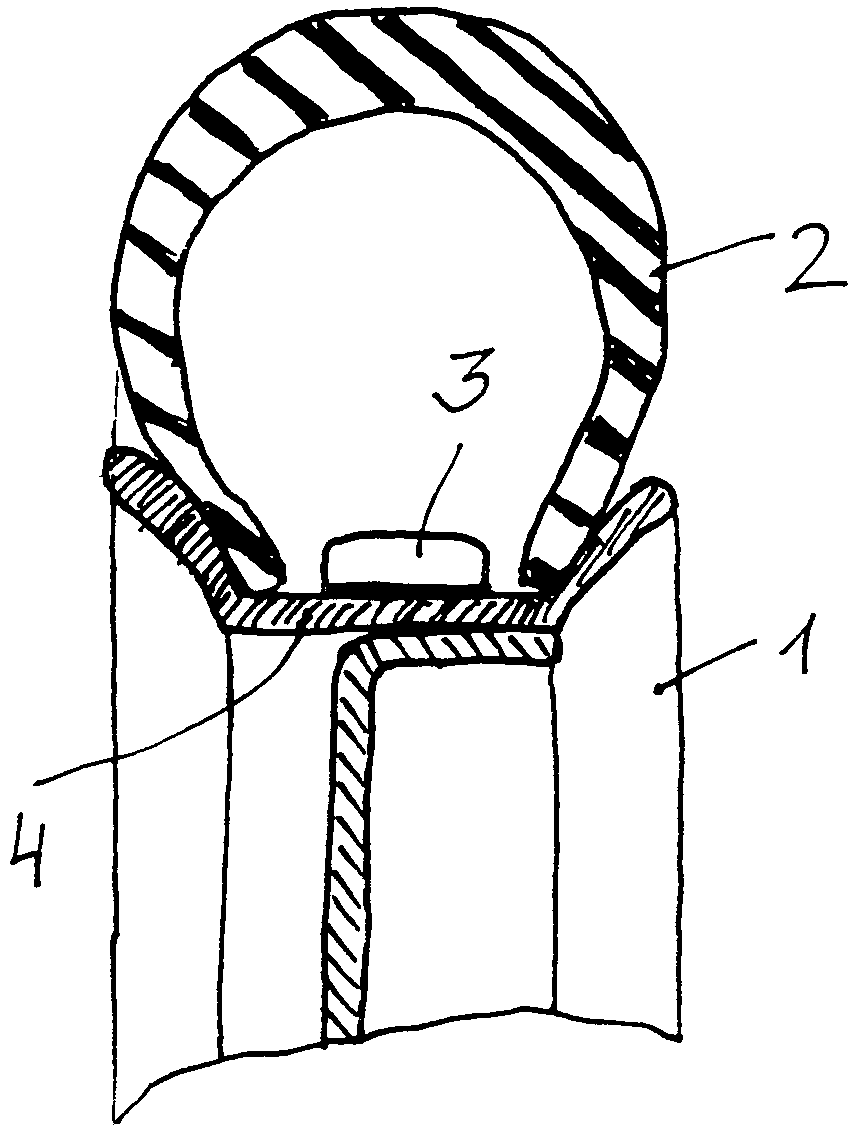
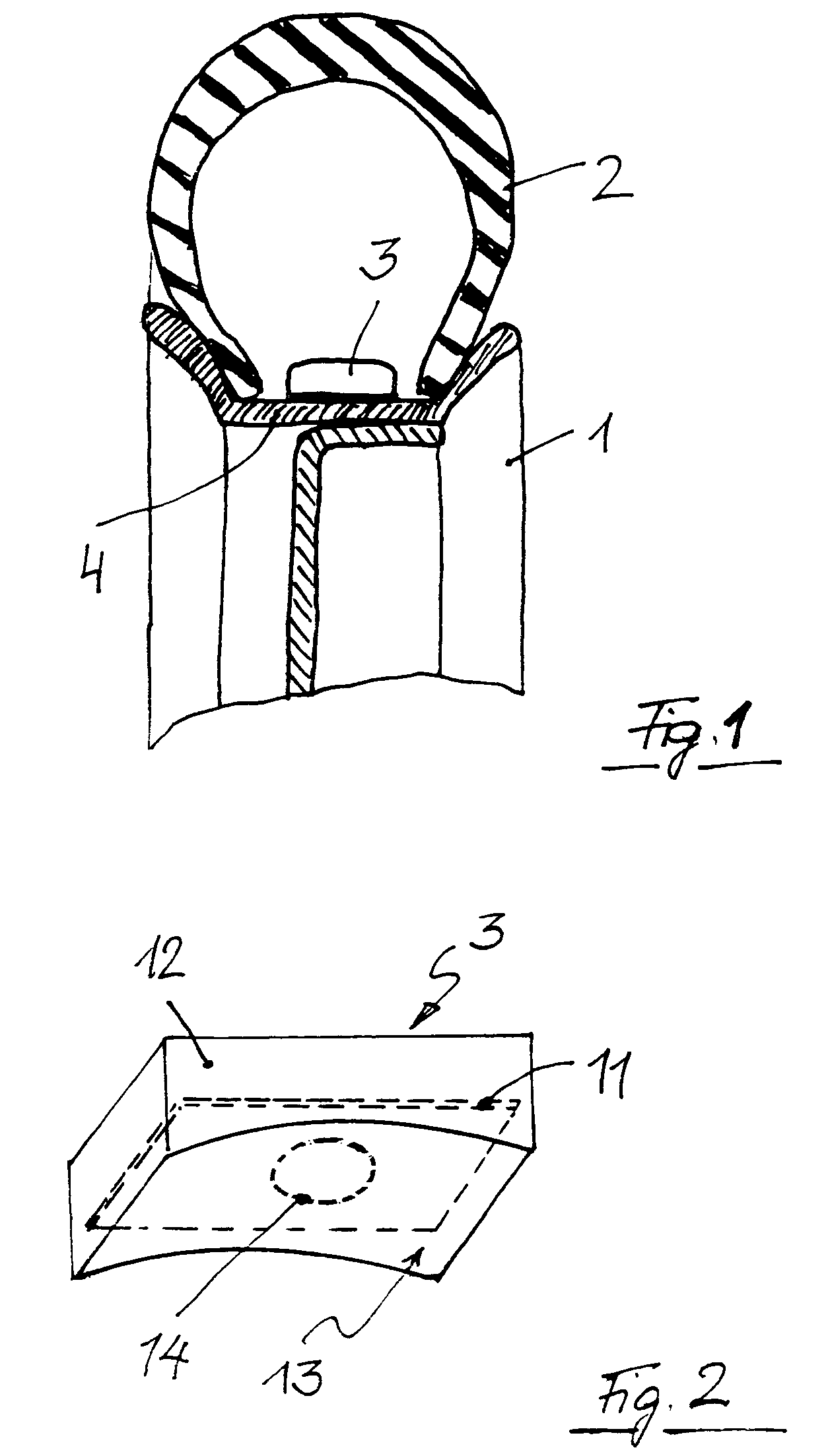
[0028]FIG. 1 shows a wheel having a rim 1 made from metal, especially from steel or aluminium. A pneumatic tire 2 is mounted on the rim 1. A wheel sensor 3, arranged below the pneumatic tire 2, is mounted on the rim base 4, for example by bonding. The wheel sensor 3 mainly serves for monitoring air pressure in the tire 2 and comprises for this purpose a pressure sensor, preferably also a temperature sensor and an acceleration sensor, further a control circuit equipped with a microprocessor or an ASIC, and means for signaling the values so measured by means of a radio transmitter and an antenna. The measured values obtained are digitally encoded, supplemented by an identification code defining the particular wheel sensor 3, and are transmitted by radio via a data bus to a receiver and evaluation unit arranged in the vehicle. The energy for the wheel sensor 3 is conveniently supplied by a battery 10—see FIGS. 3 and 4—but could be injected as well from the outside, by a sampling transm...


PUM


Abstract

The invention is a device comprising a device for detecting and signaling a physical value when connected to a rim (1) in a position below a pneumatic tire mounted on the rim (1), and further comprising a device to discover a detachment of the device from the rim. The invention provides that the device to discover a detachment comprises a proximity sensor responsive to the rim (1).

Description

[0001]Applicant claims priority of Application number 103 16 705.6 filed on 4 Apr. 2003 filed with the German Patent and Trademark Office.BACKGROUND OF THE INVENTION[0002]1. Field of the Invention[0003]The invention relates to a device for detecting signaling a physical value of a rim.[0004]2. Description of Related Art[0005]A device of that kind has been known from WO 03 / 011617 A1. The device described in that publication especially serves for determining and signaling an acceleration encountered at the device, the air pressure and / or the temperature prevailing in a pneumatic tire mounted on the rim. Such a device, which will be described hereafter also as wheel sensor, usually determines the air pressure, acceleration values and / or the temperature at predetermined time intervals, and transmits them at predetermined time intervals equal or greater than the time intervals between the measurements, or else immediately when given threshold values are exceeded, to a receiver and evalua...

Claims


Application Information

Patent Timeline
Patent Type & Authority Patents(United States)
IPC IPC(8): G01M17/02B60C23/04
CPCB60C23/0408
Inventor SCHULZE, GUNTHER LOTHAR
Owner HUF BAOLONG ELECTRONICS BRETTEN GMBH
Why Eureka
Try Eureka