
Congestion-adaptive compression

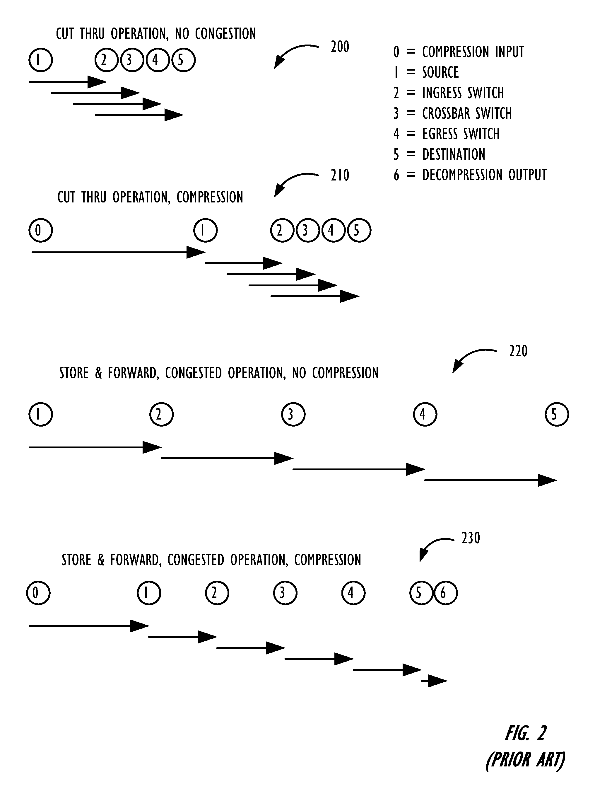
a compression and compression technology, applied in the field of network work, can solve the problems of increasing latency and low end-to-end latency in congested networks

Active Publication Date: 2011-03-10
AVAGO TECH INT SALES PTE LTD
View PDF26 Cites 37 Cited by
  • Summary
  • Abstract
  • Description
  • Claims
  • Application Information

AI Technical Summary

Benefits of technology

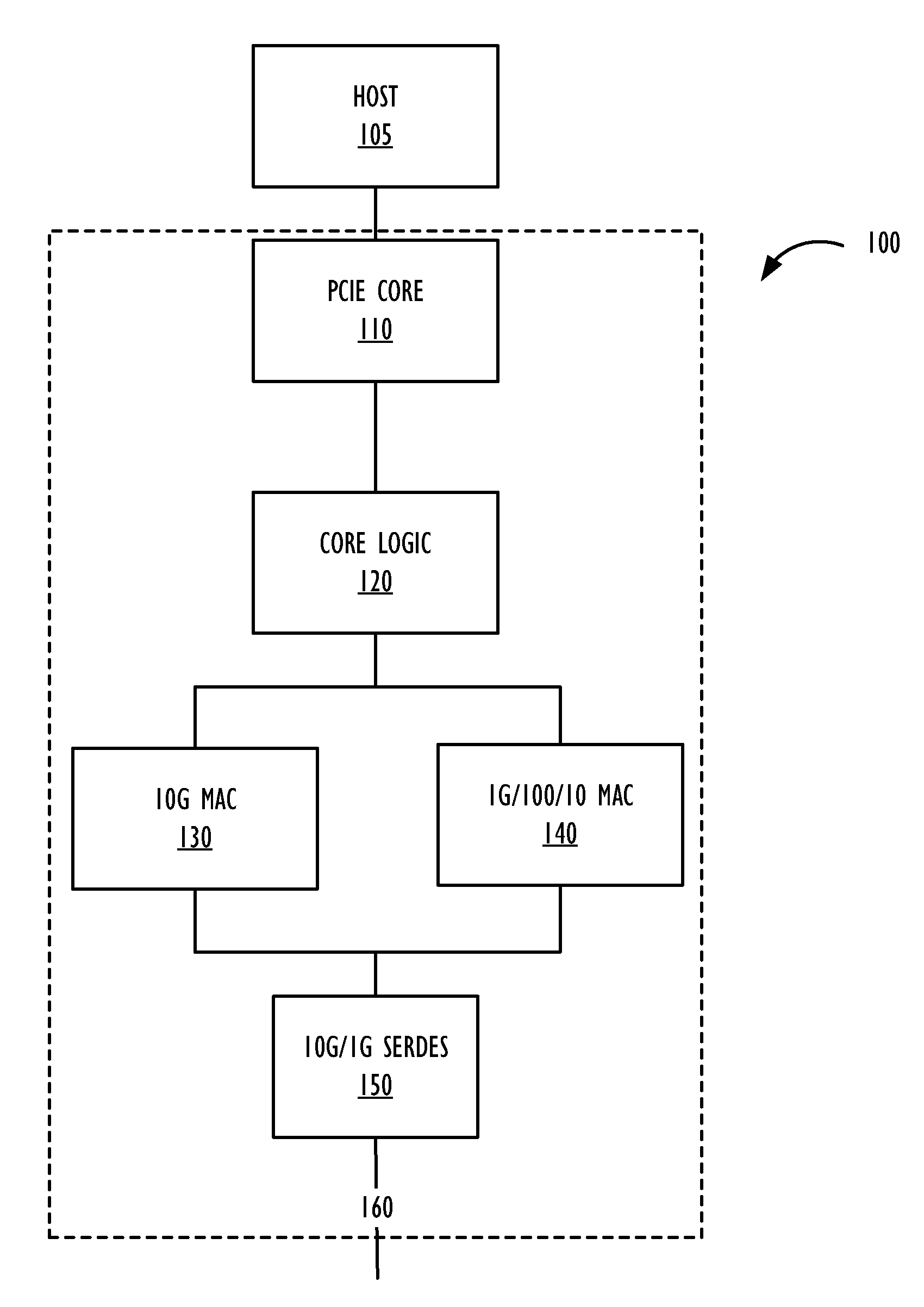
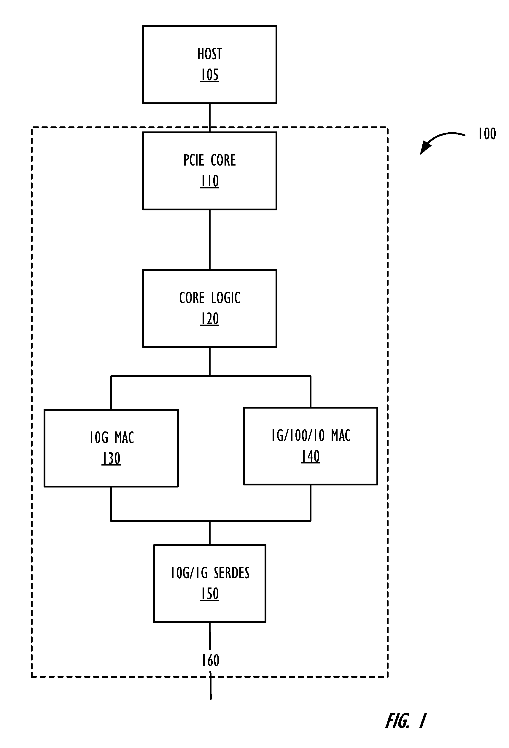
[0003]The described techniques allow a network device to compress an output data stream adaptively based on indications of network congestion. These indications can include simple pause notifications or more complex congestion notifications that indicate a quantized level of congestion, allowing finer control over the compression of data by the network device.
[0005]In embodiments where quantized levels of compression are indicated in congestion messages, when the congestion level increases, the congestion technique can be adapted to increase compression. When the congestion level decreases, the congestion technique can be adapted to decrease compression, or even disable compression altogether. The adaptive compression technique can thus achieve a lower end-to-end latency across the network.
[0007]The compression engine can respond to an indication of a quantized level of congestion by adapting the compression engine to alter one or more of the size of the string being matched, the hash table memory, and the history buffer, as well as altering the number of repetitions of compression. In addition, the compression engine can selectively perform an entropy encoding of the compressed data, resulting in further compression. All of these adaptations can be performed responsive to a quantized level of congestion, in order to vary the compression ratio, increasing the compression when congestion increases and decreasing the compression when congestion decreases.

Problems solved by technology

Compression can result in lower end-to-end latency in congested networks, but may increase latency in other situations, such as uncongested networks.

Method used


Image

  • Congestion-adaptive compression
  • Congestion-adaptive compression
  • Congestion-adaptive compression

Examples


example 2

[0051]a b c d a b c d a b c d

[0052]could be replaced with:

[0053]a b c d {4,8}

[0054]In this example, the length field is longer than the distance field, indicating that the pattern repeats from the start after every four bytes.

example 3

[0055]a a a a a a a a a a a a

[0056]could be replaced with: a {1,11}

example 4

[0057]a b a b a b a b a b c d

[0058]could be replaced by

[0059]a b {2,8} c d

[0060]In certain situations, a pattern may have occurred multiple times, and may have repeated in variable lengths. For example,

[0061]a b c d e f g h i d e f g h a b c d e f g h i

[0062]could be replaced by

[0063]a b c d e f g h i {6,5} {14,3} {8,5}i

[0064]or

[0065]a b c d e f g h i {6,5} {14,9}

[0066]Both solutions are correct but the second one results in better compression.

[0067]The distance and length vector typically comprises a match code word. The decompression technique finds the match codes, reads the location that is pointed to by the distance field, and then reads the number of bytes indicated by the length field. The decompression logic needs a way of identifying whether a particular byte is part of a literal (uncompressed) data, or is part of a match code word. In addition, code words can be inserted into the byte pattern to help the decompression logic determine the string boundaries. Preferably, the ...


PUM


Abstract

A network device is adaptively configured to compress an output data stream, responsive to congestion in the network. The network device receives indications of network congestion from another network device. Upon receipt of a congestion indication, the network device can adapt the compression technique to attempt to achieve more or less compression, depending on whether the congestion indication indicates more or less congestion. By adapting the compression to the level of network congestion, end-to-end latency of the network can potentially be decreased.

Description

TECHNICAL FIELD[0001]The present invention relates to the field of networking, and in particular to data compression techniques in a possibly congested network.BACKGROUND ART[0002]Compressing packet data can result in less congestion in a network, especially in oversubscribed situations. Congestion is reduced because a compressed packet takes less time on the wire and takes less buffer space to store. On a typical switch configuration of 24 slower speed links trunked onto an oversubscribed pair of higher speed ports, even a 20% compression can make the switch an entirely non-blocking switch. Compression can result in lower end-to-end latency in congested networks, but may increase latency in other situations, such as uncongested networks.SUMMARY OF INVENTION[0003]The described techniques allow a network device to compress an output data stream adaptively based on indications of network congestion. These indications can include simple pause notifications or more complex congestion no...

Claims


Application Information

Patent Timeline
Patent Type & Authority Applications(United States)
IPC IPC(8): H04L12/56
CPCH04L45/745H04L47/263H04L69/04H04L65/605H04L65/80H04L47/38H04L65/765
Inventor NAGAPUDI, VENKATESHBICHAL, VIKRAMSATHE, SATISH PRABHAKAR
Owner AVAGO TECH INT SALES PTE LTD
Learn More