Fresnel-based beamforming for ultrasonic arrays

a beamformer and ultrasonic array technology, applied in the field of beamformer technology, can solve the problems of reducing computational demands, requiring a significant amount of hardware and processing capability, and requiring expensive and bulky beamformers

Active Publication Date: 2011-03-10
UNIV OF SOUTHERN CALIFORNIA
View PDF24 Cites 59 Cited by
  • Summary
  • Abstract
  • Description
  • Claims
  • Application Information

AI Technical Summary

Benefits of technology

[0016]An ultrasonic beamformer may substantially compensate for differences in distances between ultrasonic elements in an ultrasonic transducer array and a location remote from the ultrasonic transducer array from which a reflected broadband pulse is received by each of the ultrasonic elements. The ultrasonic beamformer may include an input signal line for each of the ultrasonic elements configured to carry the broadband pulse from the ultrasonic element. The ultrasonic beamformer may also include a number of signal shifters that is substantially less than the number of transducer elements. Each signal shifter may be configured to shift a broadband pulse in a way that is different from the way the other signal shifters are configured to shift a broadband pulse. For each of the input signal lines, a multiplexer may be configured to electrically connect the broadband pulse received on the input signal line to a selected one of the signal shifters. The selected one may be based on a control signal. A multiplexer controller may be configured to generate the control signal for each of the multiplexers in a fashion that causes the ultrasonic beamformer to substantially compensate for the differences in the distances.

Problems solved by technology

However, these can require expensive and bulky beamformers.
This method may be straightforward and intuitive, but may require a significant amount of hardware and processing capability.
This method may reduce the computational demands compared to DAS beamforming, but may still require redundant hardware for each channel.

Method used


Image

  • Fresnel-based beamforming for ultrasonic arrays
  • Fresnel-based beamforming for ultrasonic arrays
  • Fresnel-based beamforming for ultrasonic arrays

Examples


Embodiment Construction

[0059]Illustrative embodiments are now discussed. Other embodiments may be used in addition or instead. Details which may be apparent or unnecessary may be omitted to save space or for a more effective presentation. Conversely, some embodiments may be practiced without all of the details which are disclosed.

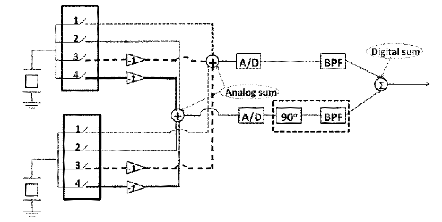
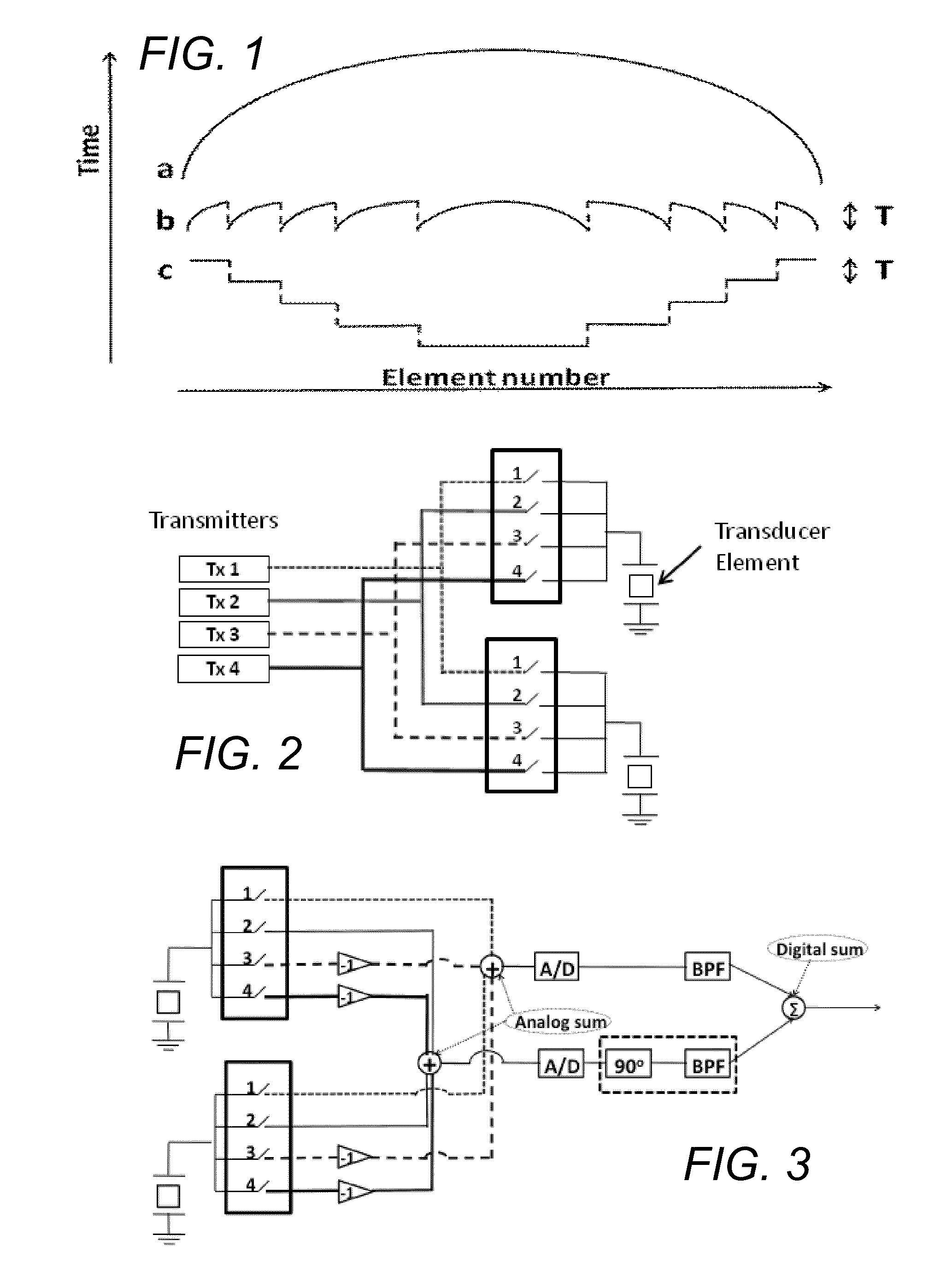
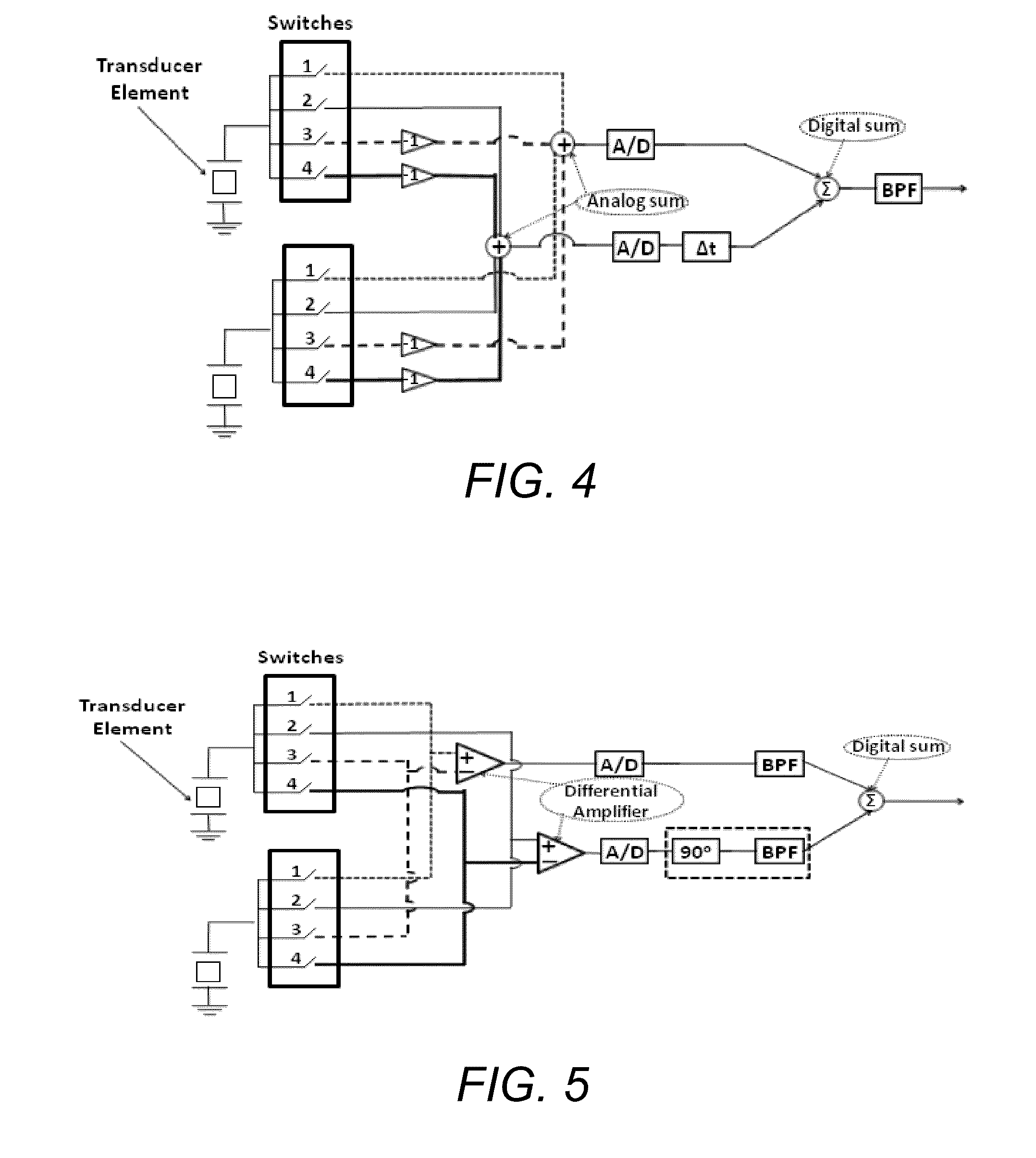
[0060]Modified, electronic, Fresnel-based beamforming technology is now described. The approaches may include a combination of analog and digital beamforming techniques.

[0061]The discussion includes two versions of Fresnel beamforming: a 4-phase (4 different time delays or phase shifts) and an 8-phase (8 different time delays or phase shifts). These are merely illustrative. Using this technology, a system with 4 to 8 transmit channels and 2 receive channels with a network of switches may be used to focus an array with 64 to 128 or even more elements. A different number of phases and channels may be used instead.

[0062]The simulation and experimental results suggest that Fresnel be...


PUM


Abstract

An ultrasonic beamformer may include an input signal line for each ultrasonic transducer element configured to carry a broadband pulse from the ultrasonic element. The ultrasonic beamformer may include a number of signal shifters that is substantially less than the number of transducer elements. Each signal shifter may be configured to shift a broadband pulse in a way that is different from the way the other signal shifters are configured to shift a broadband pulse. For each of the input signal lines, a multiplexer may be configured to electrically connect the broadband pulse received on the input signal line to a selected one of the signal shifters. A multiplexer controller may be configured to generate the control signal for each of the multiplexers in a fashion that causes the ultrasonic beamformer to substantially compensate for the differences in the distances. A comparable configuration may be used for transmission.

Description

CROSS-REFERENCE TO RELATED APPLICATION[S][0001]This application is based upon and claims priority to U.S. provisional patent application 61 / 240,122, entitled “MINIATURIZED ULTRASOUND IMAGING SYSTEM,” filed Sep. 4, 2009, attorney docket number 028080-0508. The entire content of this application is incorporated herein by reference.BACKGROUND[0002]1. Technical Field[0003]This application relates to beamforming technologies that may be used in connection with portable ultrasound systems.[0004]2. Description of Related Art[0005]In recent years, a segment of the ultrasound community has focused on making ultrasound systems which are smaller, cheaper, and more power-efficient, while maintaining good image quality. These hand-held systems can become “ultrasonic stethoscopes” that allow physicians to perform ultrasound examinations almost anywhere and at anytime. See J. R. T. C. Roelandt, “Ultrasound stethoscopy: A renaissance of the physical examination?,”Heart, vol. 89, pp. 971-974, 2003; ...

Claims


Application Information

Patent Timeline
Patent Type & Authority Applications(United States)
IPC IPC(8): A61B8/14
CPCG10K11/341G01S7/52025G01S7/5202
Inventor YEN, JESSEMUNG, JAYNGUYEN, MAN
Owner UNIV OF SOUTHERN CALIFORNIA
Why Eureka
Try Eureka