Instant reading oil dipstick improvements

a technology of oil dipsticks and oil levels, which is applied in the direction of liquid/fluent solid measurement, instruments, machines/engines, etc., can solve the problems of difficult to see new oil, oil level using conventional metal dipsticks cannot be read without wiping, etc., and achieves the effect of reducing the grip, increasing the grip, and increasing the binding fit of brass slide valves

Inactive Publication Date: 2011-03-17
ARMISTEAD JOHN ANDERSON
View PDF13 Cites 10 Cited by
  • Summary
  • Abstract
  • Description
  • Claims
  • Application Information

AI Technical Summary

Benefits of technology

[0011]Though the oil level is read through the clear plastic tubing, a film of oil would still adhere to the outside of the tubing, as in the prior invention. In some cases the outside oil film partially rubs off at the top of the metal tubing, reducing the grip needed to actuate the air valve when the dipstick is withdrawn. In order to clean oil from the outside of the plastic tube, a cone-shaped rubber squeegee, if so required, can be held in place by a split-cylinder metal spring clip that can be fitted inside the metal tube, just below the flared tubing portion, if any. The lower I. D. of the cone is smaller than the plastic tubing O. D., and automatically removes outside oil from such as the dipstick is being withdrawn. The larger I. D. of the upper squeegee portion allows the easy reinsertion of the dipstick after taking the oil level reading. In addition, the binding fit of the brass slide valve will be increased by having a fine spiral groove along the entire outside of the cone that will increase the grip, even if some loose oil gets onto the upper lip of the metal dipstick tube on vehicles.
[0012]Typically, dipsticks are about two feet long. The single Sectional View drawing which embodies the Instant Reading Oil Dipstick Improvements has correct proportions except that the tubing length is truncated or shortened. The salient features of the dipstick are shown in a longitudinal cut through the diameter of the cylindrical tubes and valve parts. Also, the oil dipstick is shown as a straight part. In actuality, most metal dipstick tubes are curved. The tempered, stainless steel wire inside the plastic tube allows the assembly to bend, easily, to conform to the curvature of most metal dipstick tubes. But the Instant Reading Oil Dipstick will return to straightness when it is withdrawn, as for measuring the oil level.

Problems solved by technology

Experience has shown that new oil, in particular, can be difficult to see, especially under poor light conditions.
And the oil level using conventional metal dipsticks can't be read without wiping off, reinserting and withdrawing the dipstick one or more times to see where the film of oil comes to on such dipstick type.

Method used


Image

  • Instant reading oil dipstick improvements
  • Instant reading oil dipstick improvements

Examples


Embodiment Construction

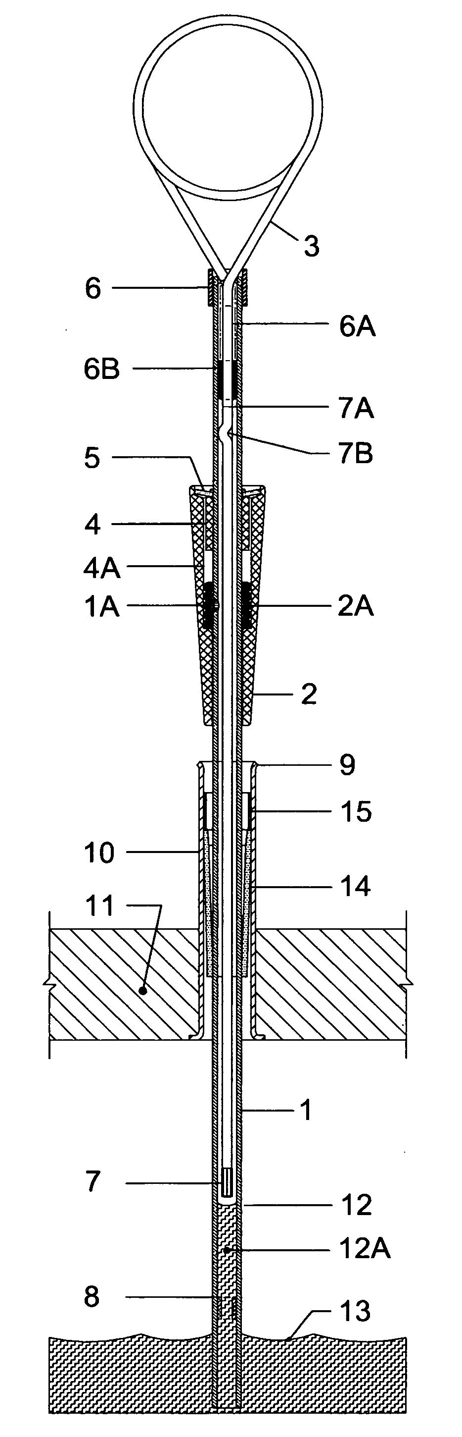
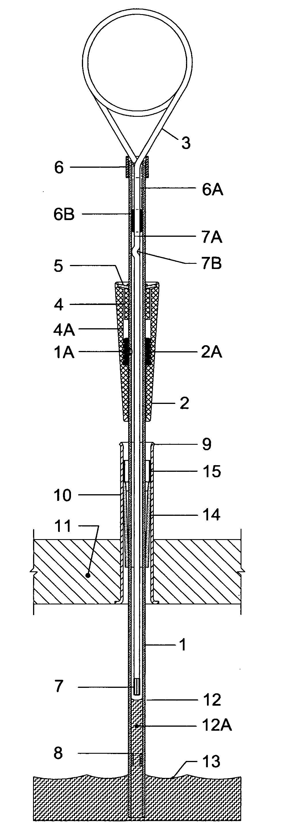
[0013]The level of engine oil, 13, inside of a crankcase, 11, can be read by inserting a clear fluoroplastic tube, 1, through metal dipstick tube, 10, and into the oil, 13. Upon lifting the wire handle, 3, which has been made airtight to the tubing, 1, via a short, concentric section of plastic tubing, 6B, the air valve inside of brass cone, 2, closes over vent hole 1A. Brass tubing trim, 6, reinforces the mechanical connection and / or helps to maintain the integrity of glue, 6A. With the air unable to escape the tube, 1, through the vent hole 1A, because of the five O-rings, 2A, two above and two below vent hole, 1A, a slug of oil, 12A, between FULL line, 7, and ADD line, 8, can be extracted from crankcase, 11, giving a true indication of the level of oil, 13, inside of crankcase, 11.

[0014]The air valve inside of brass cone, 2, has a free up and down motion of 3 / 16″, which corresponds to the distance between the centerline of the vent hole, 1A, and the center O-ring of 2A, when the ...


PUM


Abstract

Instant Reading Oil Dipstick Improvements is a near universal design with most assembly done by the manufacturer. The customers can easily adapt such to match their existing dipstick geometry by pushing the adjustable parts to the correct location, where they will remain. The air valve is within a single, machined brass cone that adapts to the metal tube and seals in the engine vacuum. A new tubular plastic air seal around the wire handle increases reliability. And a cone shaped rubber squeegee will automatically remove oil from the outside of the tubing as the dipstick is withdrawn from the crankcase.

Description

[0001]“This is a division [continuation] of design application No. 12 / 288,399, filed Oct. 21, 2008.” Such prior application was named INSTANT READING OIL DIPSTICK. It is intended that the present application include the collective product development that will be embodied in the first commercial introduction of the product. Therefore, the present application will describe the total invention as presently developed, including the salient earlier claims that are still applicable.BACKGROUND OF THE INVENTION[0002]The objective of both the prior Instant Reading Oil Dipstick invention, and the present Improvements invention, is to make reading vehicle oil levels as quick and easy as possible. Experience has shown that new oil, in particular, can be difficult to see, especially under poor light conditions. And the oil level using conventional metal dipsticks can't be read without wiping off, reinserting and withdrawing the dipstick one or more times to see where the film of oil comes to on...

Claims


Application Information

Patent Timeline
Patent Type & Authority Applications(United States)
IPC IPC(8): G01F23/04
CPCG01F23/04A43C7/005
Inventor ARMISTEAD, JOHN ANDERSON
Owner ARMISTEAD JOHN ANDERSON
Why Eureka
Try Eureka