
Magnetic refrigerator

a refrigerator and magnetic technology, applied in the field of magnetic refrigerators, can solve the problems of large volume, high noise, and the inability to recoil magnetic refrigerators, and achieve the effects of reducing the load of the driving device, eliminating the reverse torque, and reducing the nois

Inactive Publication Date: 2011-03-17
DELTA ELECTRONICS INC
View PDF12 Cites 53 Cited by
  • Summary
  • Abstract
  • Description
  • Claims
  • Application Information

AI Technical Summary

Benefits of technology

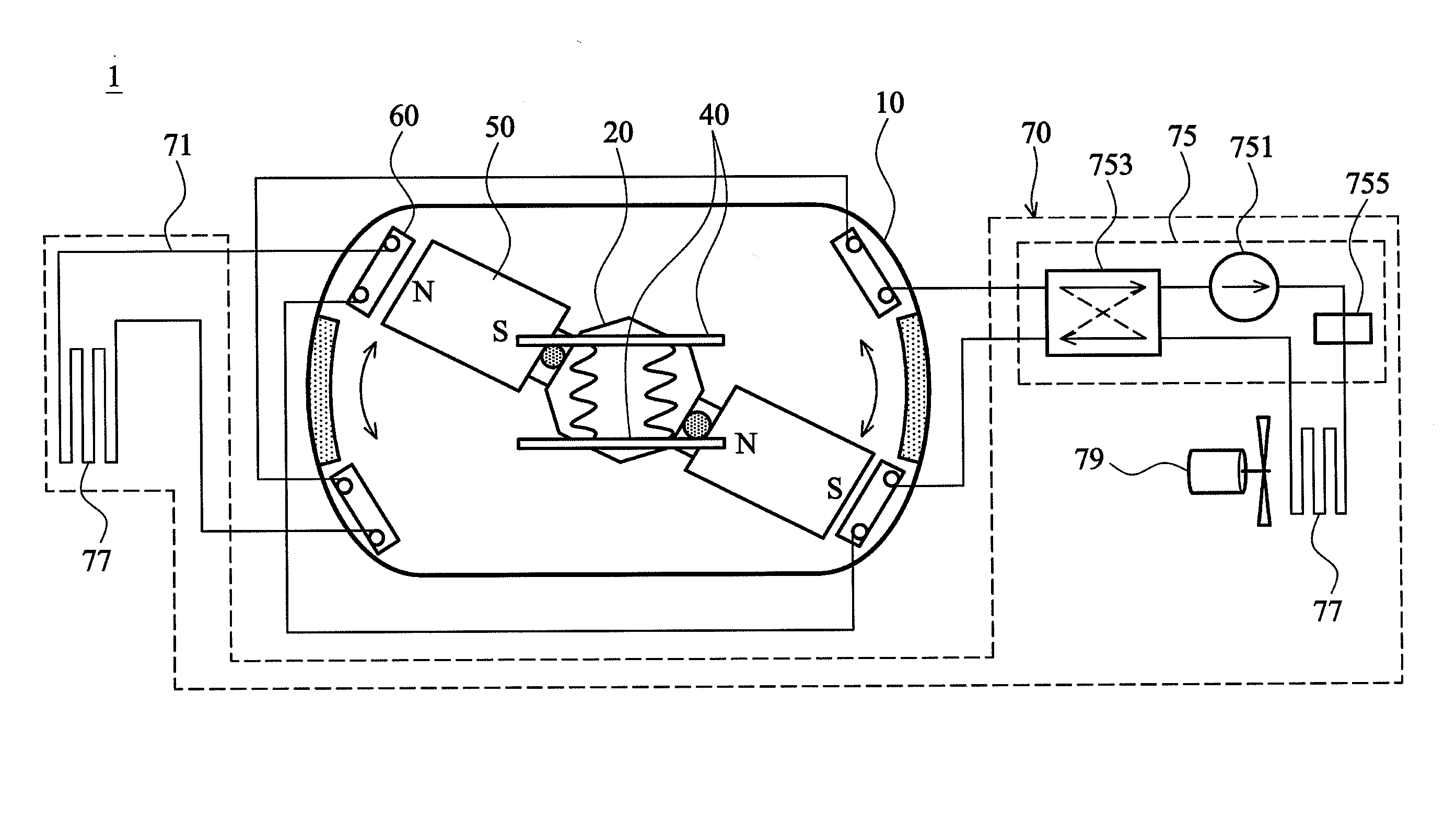
[0010]In addition, the invention also discloses a driving device disposed at one side of the magnetic refrigerator, wherein the driving device may comprising or not comprising a decelerating device to drive the shaft moving back and forth between pairs of working pieces. There is a magnetic structure disposed on the shaft so as to oscillate with the shaft when the shaft is driven by the driving device. Furthermore, in order to eliminate loading of the driving device, this invention provides a torque eliminating device disposed at both sides of the surface of the body to eliminate reverse torque when the driving device reverses the shaft. The torque eliminating device controls route of the shaft and provides sufficient buffer, especially timing of brake, for the shaft while the shaft is driven moving back and forth by the driving device hence the magnetic refrigerator has the best working efficiency.
[0011]In an embodiment of the invention, for getting stronger magnetic field, the magnetic structure is changed into U-Shape, wherein three permanent magnets with different magnetic pole directions are combined to form the U-shaped magnetic structure, and the mouth of the U-shaped magnetic structure comprising soft magnetic ferrite faces the working piece to enhance magnetic field toward the working pieces so as to enhance efficiency of freezing. Besides, there can be attached a plurality of auxiliary soft iron around the U-shaped magnetic unit to further enhance total magnetic field, and so as to unify magnetic lines surround the working pieces.

Problems solved by technology

However, reciprocating magnetic refrigerator has some drawbacks such as large volume, high noise and low reliability.
On the other hand, rotating magnetic refrigerator (referred to Japan patent number 2008-51409) has some drawbacks such as large torque, high loading and difficulty in setting torque eliminating devices.

Method used


Image

  • Magnetic refrigerator
  • Magnetic refrigerator
  • Magnetic refrigerator

Examples


Embodiment Construction

[0021]The present invention will be apparent from the following detailed description, which proceeds with reference to the accompanying drawings, wherein the same references relate to the same elements.

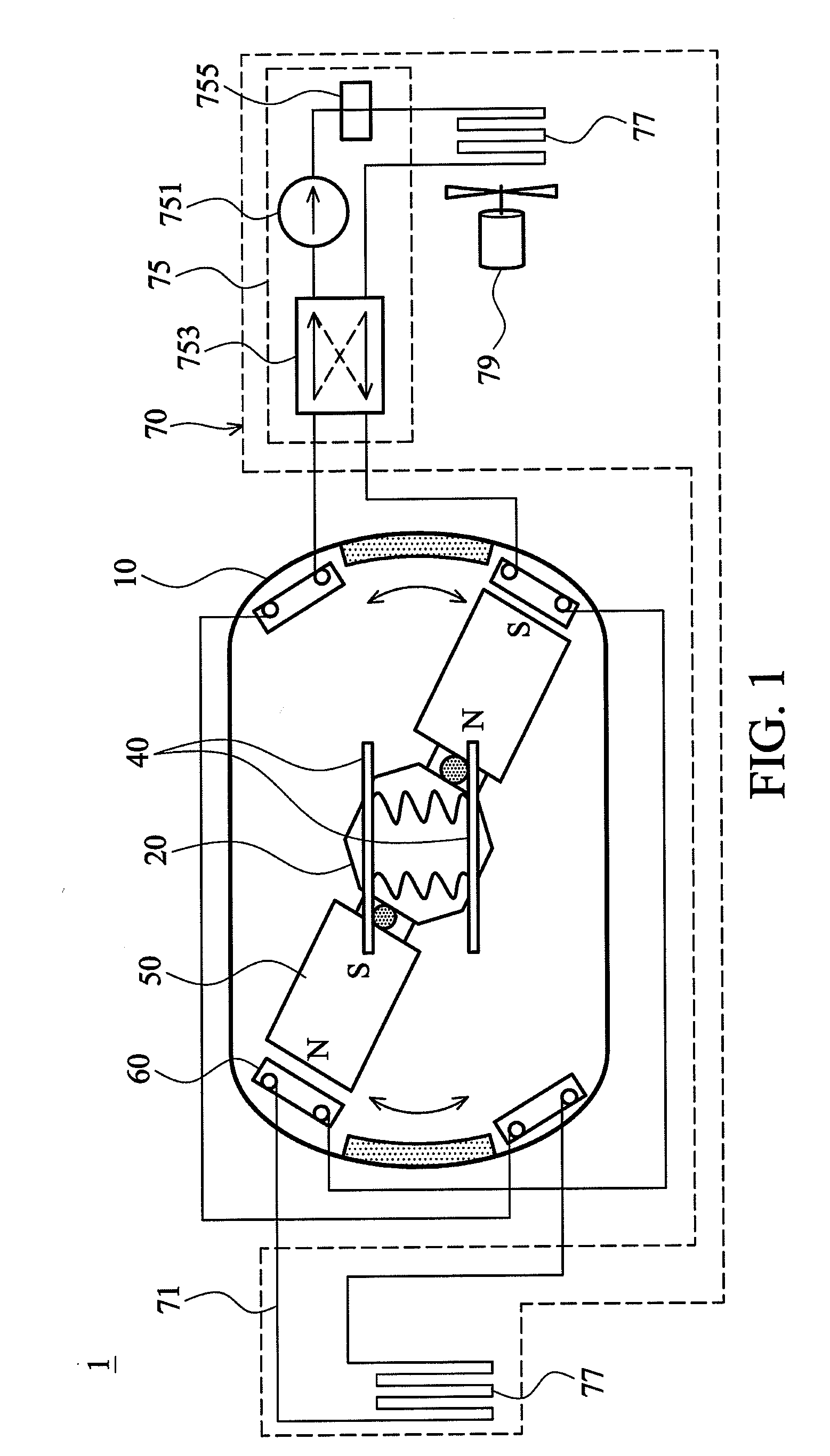
[0022]This invention is related to a magnetic refrigerator which has smaller volume, less power consumption and more freezing capability. Please refer to FIG. 1, the magnetic refrigerator 1 at least comprises a body 10, a shaft 20, a driving device 30 (as shown in FIG. 6C), a torque eliminating device 40, a magnetic structure 50, a plurality of working pieces 60 and a heat dissipating unit 70.

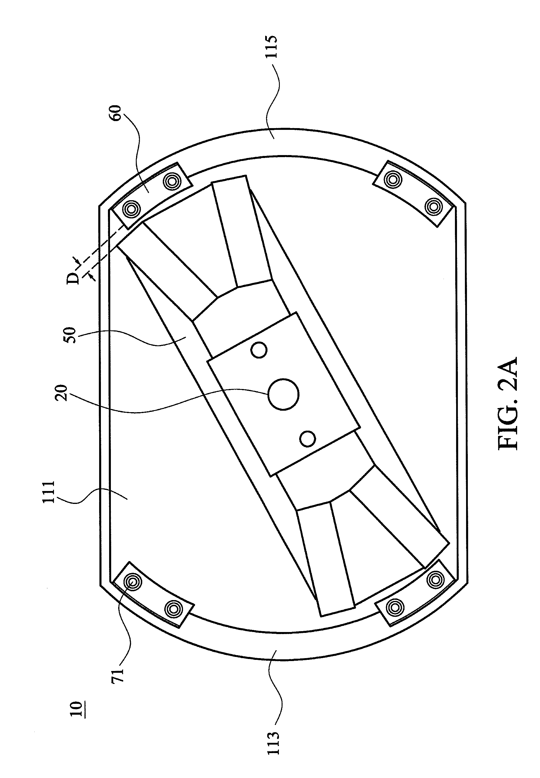
[0023]Please further refer to FIG. 2A, wherein the body 10 is a hollow body made by, for example, magnetic conductive materials. The shaft 20 is disposed substantially at the center inside of the body 10 and partially penetrated a first side wall 111 of the body 10 to be connected to the driving device 30 (as shown in FIG. 6C), wherein the driving device 30 is adapted to be connected with a part ...


PUM


Abstract

A magnetic refrigerator has reciprocated and rotated motions. The body of the apparatus has a nearly tubular shape and contains working pieces at corners, wherein the working pieces surround a shaft with permanent magnet. Compared with existing rotational models, the magnetic refrigerator of the present invention has a relative smaller volume, and the motion of the shaft will be back and forth. Furthermore, a torque eliminating device of the magnetic refrigerator will eliminate the reverse torque when the shaft is driven reverse so that improve cooling efficiency.

Description

CROSS REFERENCE TO RELATED APPLICATIONS[0001]This application claims the benefit of U.S. Provisional Application No. 61,243,384, filed Sep. 17, 2009.BACKGROUND OF THE INVENTION[0002]1. Field of the Invention[0003]The invention relates to a refrigerator, especially to a magnetic refrigerator which adapting magneto-caloric material.[0004]2. Description of the Related Art[0005]As mentioned to nowadays' technology development, well-known magnetic refrigerators are roughly divided into two fields, reciprocating and rotating models. The reciprocating magnetic refrigerator, for example, disclosed by U.S. Pat. No. 5,934,078 patent has regenerator beds disposed at the center shaft, and adapts a driving machine to drive the shaft to do reciprocated motion in an axis horizontally or vertically, and force the regenerator beds into or out off a magnetic field so as to magnetize or demagnetize magneto-caloric material (MCM) periodically. Finally, there are a hot heat exchanger and a cold heat exc...

Claims


Application Information

Patent Timeline
Patent Type & Authority Applications(United States)
IPC IPC(8): F25B21/00
CPCF25B21/00Y02B30/66F25B2321/0023F25B2321/0022Y02B30/00
Inventor SHIH, CHENG-YENSHEU, GWO-JIUNHSU, MAO-JENMENG, SHI-PIN
Owner DELTA ELECTRONICS INC
Learn More