Desiccant regeneration

a technology of desiccant and regeneration, which is applied in the direction of separation process, dispersed particle separation, chemistry apparatus and processes, etc., can solve the problems of affecting the reliability of fuel system components, affecting the operation delay, and water being an unavoidable contaminant in fuel

Inactive Publication Date: 2011-03-17
AIRBUS OPERATIONS LTD
View PDF11 Cites 27 Cited by
  • Summary
  • Abstract
  • Description
  • Claims
  • Application Information

AI Technical Summary

Benefits of technology

[0012]The microwave heating of the desiccant medium has advantages over other forms of heating. Heating with an electrical heating element or a heat exchanger, for example, would heat the outer surface of the desiccant medium and transfer heat into the desiccant medium primarily by conduction. Heating by conduction would limit the rate of heat transfer and create a large temperature gradient in the desiccant medium, resulting in some areas being over-heated and some under-heated and thereby not at the optimum operating condition. By contrast, the microwaves penetrate in the medium and give more effective and uniform heating.
[0014]Whilst energizing the water in the desiccant medium will facilitate regeneration of the medium, it is also important that relatively dry air comes into contact with the desiccant medium whilst the microwave transmitter is operating to transport water vapour away from the desiccant medium. This may be effectively achieved by passing relatively dry air through the desiccant medium in a direction away from the fuel tank.
[0016]The ventilation system may further comprise a microwave energy receiver. The receiver may form part of a microwave control system connected to the transmitter and the receiver. The energy transmitted will be partially absorbed by the water present in the desiccant medium. Energy that is not absorbed by the water, or elsewhere, will be present at the receiver. As the water content varies, the amount of energy absorbed by the water changes. Therefore, a signal from the receiver may be used to measure and control the transmitted energy level, such that the transmitted energy is kept at an optimal level to regenerate the desiccant medium. The control system may be adapted to maintain a substantially constant receive power level when the transmitter is operating. In this way, the heating effect remains constant. The amount of transmitted microwave energy is proportional to the amount of water in the desiccant such that the microwave energy per unit volume of water is constant. This ensures that the water is not heated up too rapidly by putting too much microwave energy per unit volume of water to cause high temperatures. When the desiccant is dry, the transmitted microwave energy would be zero so preventing energy wastage.
[0017]The control system may further comprise one or more temperature sensors for sensing the temperature of the desiccant medium. The control system may be adapted to stop heating when the temperature of the desiccant exceeds a predetermined level, so as to prevent degradation of the desiccant.
[0018]The dehumidifying device may further comprise a conduit, and the desiccant medium may be disposed in the conduit. The conduit may be in flow communication between the vent and the fuel tank. One or more electro-magnetic containment elements may be provided for containing the microwave energy within a region of the conduit. This ensures there is no microwave leakage to the fuel tank which may interfere with avionics, sensors and other electromechanical devices in the fuel tank. It also eliminates the possibility of unintentional heating up of fuel and other media in the fuel tank by the microwaves to a high temperature.

Problems solved by technology

Water is an unavoidable contaminant in fuel.
It can affect fuel system component reliability and lead to operational delays and increased maintenance activities.
This results a net outflow of air through the ventilation system.
This results a net inflow of ambient air through the ventilation system.
The fuel system is cold during descent as the aircraft will likely have just spent some time at cold, cruise temperatures.

Method used


Image

  • Desiccant regeneration
  • Desiccant regeneration
  • Desiccant regeneration

Examples


Embodiment Construction

)

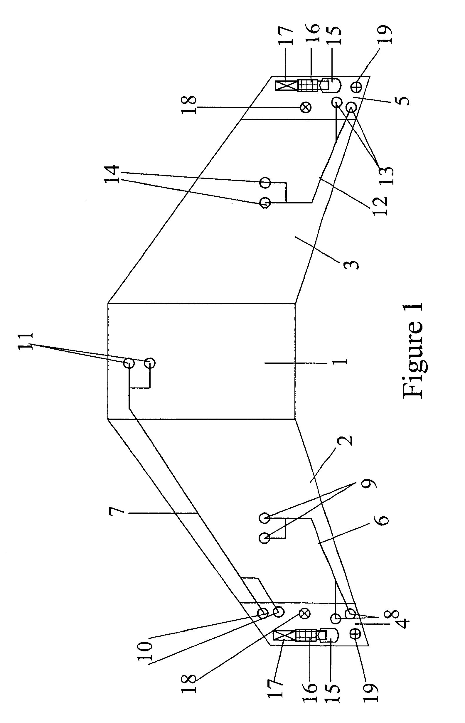
[0031]FIG. 1 shows a general ventilation system architecture for a three-tank configuration of an aircraft fuel system. The fuel system includes a centre tank 1, a left wing tank 2 and a right wing tank 3. The ventilation system includes a left vent tank 4 and a right vent tank 5. The left vent tank 4 ventilates the centre tank 1 and the left wing tank 2 by means of ventilation pipes 6, 7 which open into ventilation inlets 8, 9, 10, 11. The right vent tank 5 ventilates the right wing tank 3 by means of ventilation pipe 12 which opens into ventilation inlets 13 and 14. The centre tank could equally be vented by the right vent tank. It is to be noted that all of the fuel tanks are ventilated but are not cross-ventilated, i.e. the left and right vent tanks are not connected by ventilation paths.

[0032]Each vent tank 4, 5 includes a NACA vent, or NACA scoop, 15 which opens to the atmosphere on the lower aerodynamic surface of the aircraft wing. The vent tanks 4, 5 further include a vent...


PUM

PropertyMeasurementUnit
temperatureaaaaaaaaaa
receive power levelaaaaaaaaaa
temperatureaaaaaaaaaa

Abstract

An aircraft fuel tank ventilation system, comprising a desiccative dehumidifying device including a desiccant medium disposed in flow communication between a vent open to the atmosphere and a fuel tank, and a microwave energy transmitter for energizing liquid water in the desiccant medium to facilitate regeneration of the medium. Also, a method of regenerating a desiccant medium of a dehumidifying device of an aircraft fuel tank ventilation system, the method comprising directing air through the desiccant medium, and transmitting microwave energy into the desiccant medium for energizing liquid water in the desiccant medium to facilitate regeneration of the medium.)

Description

FIELD OF THE INVENTION[0001]The present invention relates to an aircraft fuel tank ventilation system having a desiccative dehumidifying device, and more particularly to a system and method for regenerating a desiccant medium of the dehumidifying device.BACKGROUND OF THE INVENTION[0002]Water is an unavoidable contaminant in fuel. It can affect fuel system component reliability and lead to operational delays and increased maintenance activities. In addition, the propensity for microbiological contamination is directly proportional to the presence of water and the temperature within fuel tanks. Sources of water in aircraft fuel tanks is from fuel loaded into the aircraft fuel tanks during refuel (dissolved water) and from air entering the aircraft fuel tanks via its ventilation system. It is estimated that up to 30-40% of water in the fuel of aircraft fuel tanks is currently entering via the ventilation system, depending on atmospheric conditions.[0003]During refill while the aircraft...

Claims


Application Information

Patent Timeline
Patent Type & Authority Applications(United States)
IPC IPC(8): B01D53/02
CPCB01D53/261B01D2251/404B01D2251/608B64D37/34B01D2253/116B01D2259/40094B01D2259/4575B01D2253/11
Inventor LAM, JOSEPH K-WTICHBORNE, FRANKLINMASTERS, SIMONPARMENTER, DAVID
Owner AIRBUS OPERATIONS LTD
Why Eureka
Try Eureka