

Light-extraction member, organic el element, and method for producing the organic el element
- Summary
- Abstract
- Description
- Claims
- Application Information
AI Technical Summary
Benefits of technology
Problems solved by technology
Method used
Image

Examples
example 1
Formation of Light-Emitting Part
[0172]As described below, a hole injection layer, a hole transport layer, a blue light-emitting layer, a green light-emitting layer, a red light-emitting layer, an electron transport layer, an electron injection layer and an upper electrode layer were formed in this order over a reflective electrode layer (Al) on a TFT (active matrix) substrate.
(Green Organic Compound Layer)
[0173]A hole injection layer was formed on the reflective electrode layer (anode) by vacuum-depositing 2-TNATA [4,4′,4″-tris(2-naphthylphenylamino)triphenylamine] and MnO3 at a ratio of 7:3 so as to have a thickness of 20 nm.
[0174]Next, a first hole transport layer was formed on the hole injection layer by vacuum-depositing 2-TNATA doped with F4-TCNQ is (2,3,5,6-tetrafluoro-7,7,8,8-tetracyanoquinodimethane) at a concentration of 1.0% so as to have a thickness of 141 nm.
[0175]Next, a second hole transport layer was formed on the first hole transport layer by vacuum-depositing α-NPD ...
example 2
[0220]The procedure of Example 1 was repeated, except that the same material as each color material for the color filter layer was applied on the pattern of the color filter layer instead of the same material as in the lens member, to thereby obtain organic EL element 2. Note that the light-extracting substrate had a water permeability of 0.000001 g / m2 / day.
example 3
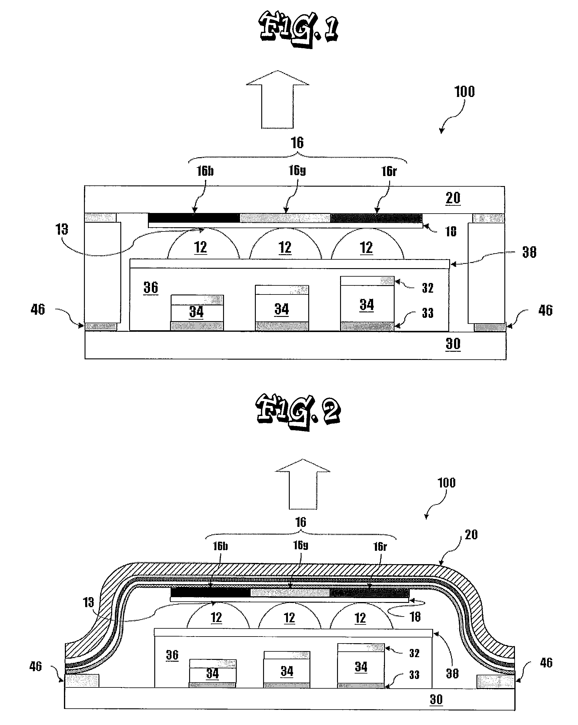
[0221]The procedure of Example 1 was repeated, except that a barrier film (trade name: TECHBARRIER HX (product of MITSUBISHI PLASTICS) having a layer structure illustrated in FIG. 2 was used as the light-extracting substrate used for forming the light-extraction member (the substrate used for forming the color filter layer), to thereby obtain organic EL element 3. Note that the light-extracting substrate had a water permeability of 0.001 g / m2 / day.
PUM
 Abstract
Description
Claims
Application Information