Power Generation Apparatus

Inactive Publication Date: 2011-03-17
ROHM CO LTD +1
View PDF8 Cites 24 Cited by
  • Summary
  • Abstract
  • Description
  • Claims
  • Application Information

AI Technical Summary

Benefits of technology

[0012]In view of the above-mentioned problem, it is an object of the present

Problems solved by technology

However, in the conventional vibration power generation apparatus described above, the generated power is approximately 10 μW, which can be used for a limited applicati

Method used


Image

  • Power Generation Apparatus
  • Power Generation Apparatus
  • Power Generation Apparatus

Examples


first embodiment

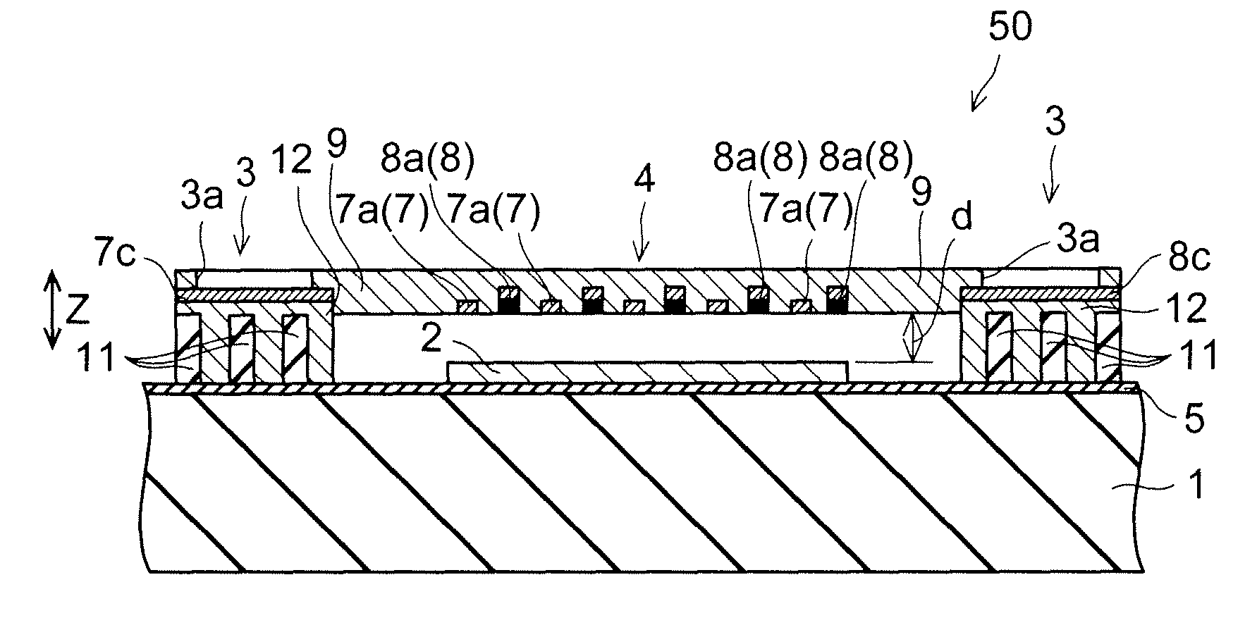
[0153]FIG. 11 is a perspective view of a structure of a power generation apparatus according to a first embodiment of the present invention. FIG. 12 is a cross sectional view cut along the line α1-α1 in FIG. 11. FIG. 13 is a plan view of the power generation apparatus according to the first embodiment of the present invention illustrated in FIG. 11. FIGS. 14 to 17 are diagrams for illustrating the structure of the power generation apparatus according to the first embodiment of the present invention. First, with reference to FIGS. 11 to 17, the structure of the power generation apparatus 50 according to the first embodiment of the present invention will be described.

[0154]The power generation apparatus 50 according to the first embodiment includes a ceramic substrate 1, a ferroelectric layer 2 formed on the ceramic substrate 1, a frame portion 3 formed on the ceramic substrate 1 so as to surround the ferroelectric layer 2, and a proof mass 4 disposed inside the frame portion 3 as ill...

second embodiment

[0195]FIG. 29 is a perspective view illustrating a structure of a power generation apparatus according to a second embodiment of the present invention. FIG. 30 is a cross sectional view cut along the line a2-a2 in FIG. 29. FIG. 31 is a plan view of the power generation apparatus according to the second embodiment of the present invention illustrated in FIG. 29. FIGS. 32 to 35 are diagrams for illustrating the structure of the power generation apparatus according to the second embodiment of the present invention. First, with reference to FIGS. 29 to 35, the structure of a power generation apparatus 60 according to the second embodiment of the present invention will be described.

[0196]The power generation apparatus 60 according to the second embodiment includes a ceramic substrate 1, a ferroelectric layer 22 formed on the ceramic substrate 1, a frame portion 23 formed on the ceramic substrate 1 so as to surround the ferroelectric layer 22, and a proof mass 24 disposed inside the frame...


PUM


Abstract

A power generation apparatus includes a dielectric, a movable member being opposed to the dielectric with a predetermined distance, and an electret and an opposing electrode that are formed on the surface of the movable member facing the dielectric so as to generate a fringe electric field penetrating the dielectric between the two electrodes. When the volume occupancy of the dielectric between the electret and the opposing electrode varies in accordance with a displacement of the movable member, the power generation apparatus outputs the electric charge induced in the opposing electrode as electric current.

Description

CROSS-REFERENCE TO RELATED APPLICATIONS[0001]This application is based on Japanese Patent Application No. 2009-213155 filed on Sep. 15, 2009.BACKGROUND OF THE INVENTION[0002]1. Field of the Invention[0003]The present invention relates to a power generation apparatus for converting kinetic energy (vibrational energy) into electric energy, and particularly to a vibration drive capacitive power generation apparatus that is manufactured by using micro electromechanical system (MEMS) technology.[0004]2. Description of Related Art[0005]FIG. 54 is a schematic diagram illustrating a conventional example of a vibration power generation apparatus that is manufactured by using the MEMS technology. The vibration power generation apparatus of the conventional example has a structure including an upper unit U1 and a lower unit U2 that are manufactured separately by using a bulk MEMS technology and then are glued to each other.[0006]In FIG. 54, numeral 100 denotes parylene (registered trademark), ...

Claims


Application Information

Patent Timeline
IPC IPC(8): H02N11/00
CPCH02N1/08
Inventor AOYAGI, SEIJIYOSHIKAWA, YASUHIRO
Owner ROHM CO LTD
Why Eureka
Try Eureka