Distance estimating device, distance estimating method, program, integrated circuit, and camera

a technology of distance estimation and distance, which is applied in closed circuit television systems, instruments, television systems, etc., can solve the problems of unsuitable triangular methods, unsuitable application, and it is difficult to uniquely determine the result of distance calculation, etc., and achieves high resolution, high frame rate, and high precision

Inactive Publication Date: 2011-03-17
PANASONIC CORP
View PDF14 Cites 33 Cited by
  • Summary
  • Abstract
  • Description
  • Claims
  • Application Information

AI Technical Summary

Benefits of technology

[0090]According to the present invention, a distance estimating device, a distance estimating method, a program, an integrated circuit and a camera, in which occurrence of saturation in the imaging elements (CCDs and the like) is suppressed, and which can obtain distance images of a high resolution and a high frame rate by using the TOF system and perform the distance estimating process of a high precision, can be achieved.

Problems solved by technology

Thus, it takes a relatively long time till the three dimensional information is obtained for the entire target space.
Therefore, the triangular method is said to be unsuitable for application such as tracking a moving object, or the like.
In such a case, there is a problem that, based on Equation 2, when the distance to the measurement object equals to or longer than a wavelength corresponding to a cycle of intensity modulation of the measurement light beam, it is theoretically impossible to uniquely determine the result of the distance calculation (i.e., the distance to the measurement object cannot be specified).
On the other hand, in the pulse TOF system, there is a problem that a time period required for obtaining the distance image becomes long since it is necessary to physically scan with the measurement light beam such as laser light or the like emitted from the light source in vertical and horizontal directions using a wobble mirror, polygon mirror, or the like for obtaining the distance image by scanning with the measurement light beam in a two dimensional manner.
However, the brightness of the imaged picture A is affected by reflectance of the objects, spatial nonuniformity of the irradiation light amount, damping effects due to distances in the diffused reflected light amount, and the like.
However, since the distance estimating device 900 needs to secure a certain degree of light intensity of the light reflected from the objects, light sources such as light emitting diode array consisting of a plurality of light emitting diodes or the like has to be used, resulting in a disadvantage that the size of the device becomes large.
The distance estimating device 950 of Conventional Example 2 is small and has a high resolution, but has a disadvantage that the imaged picture (video) has low resolution and low frame rate.

Method used


Image

  • Distance estimating device, distance estimating method, program, integrated circuit, and camera
  • Distance estimating device, distance estimating method, program, integrated circuit, and camera
  • Distance estimating device, distance estimating method, program, integrated circuit, and camera

Examples


first embodiment

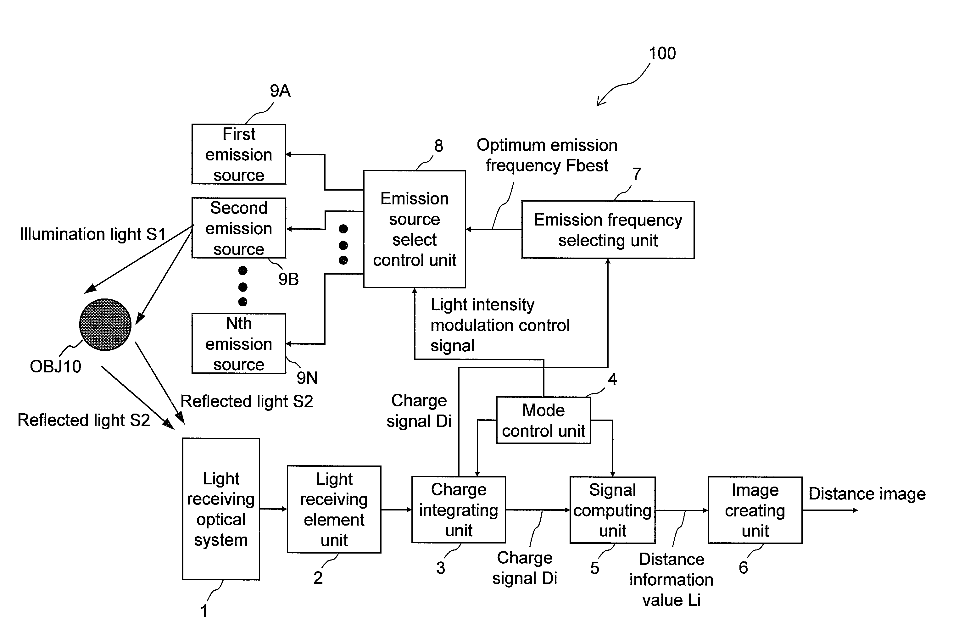
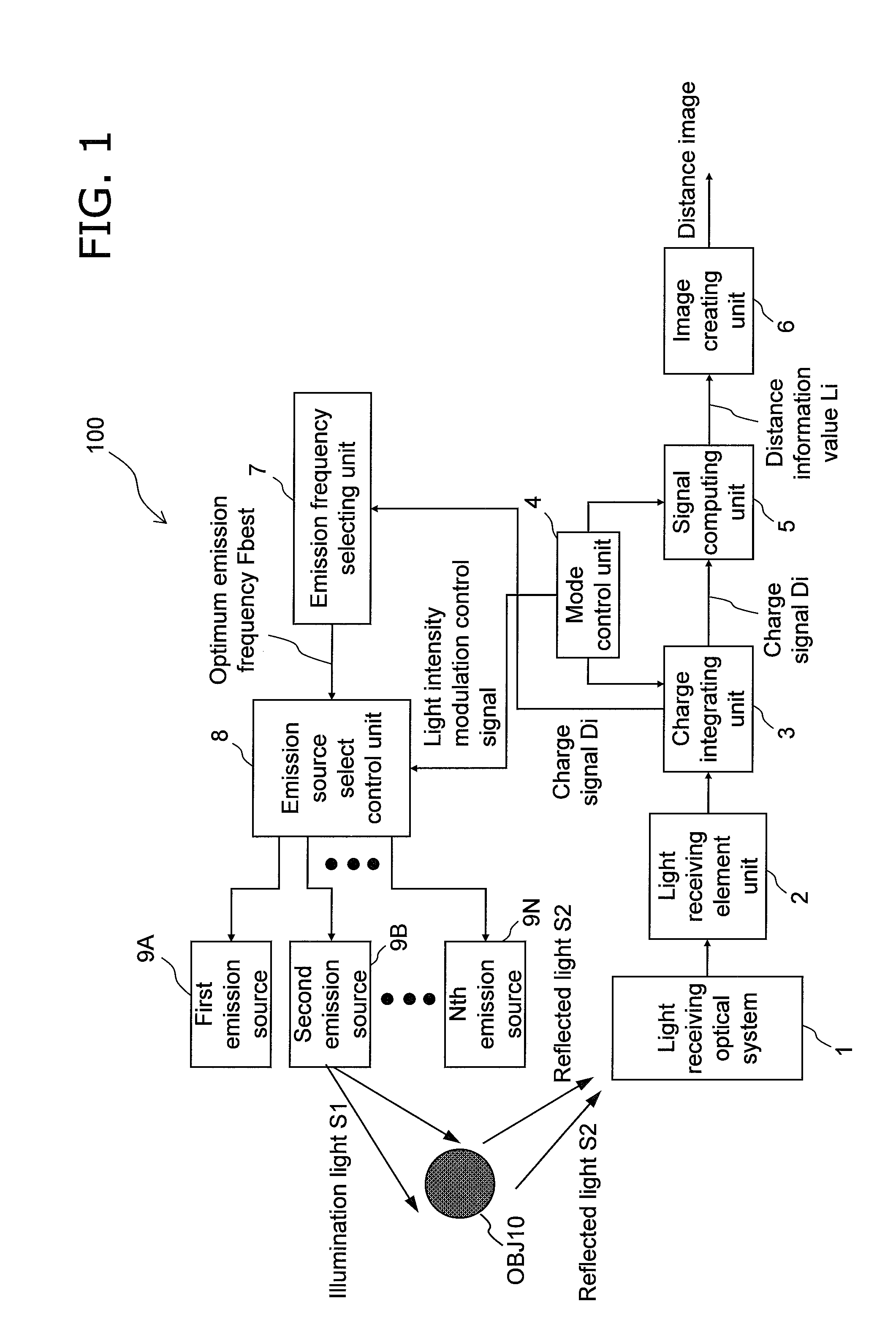
[0124]With reference to FIGS. 1 through 5, a distance estimating device and a distance estimating method, in which light reflected from an object with no light being emitted from the light source is received, illumination light having an emission frequency which is insusceptible to environment light is selected based on a result of a frequency analysis of the reflected light, and the illumination light having the selected emission frequency is used to obtain a distance image to the object, are described as the first embodiment of the present invention.

[0125]

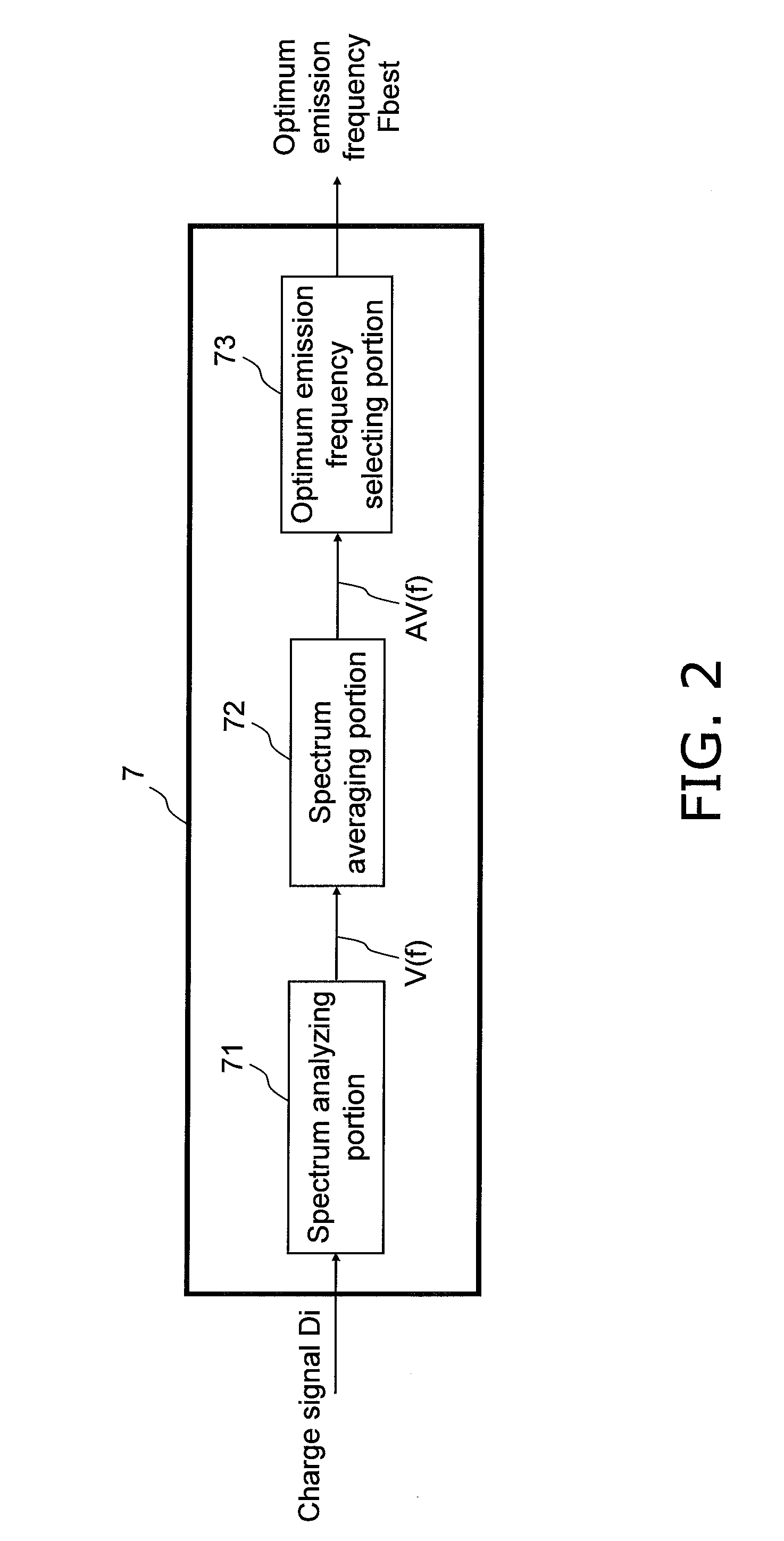
[0126]FIG. 1 is a schematic block diagram of a distance estimating device 100 according to the first embodiment of the present invention. FIG. 2 is a diagram showing a structure of an emission frequency selecting unit 7 in the distance estimating device which is an example of the first embodiment of the present invention. FIG. 3 is a diagram showing an outline of a method for selecting an emission frequency of a light source in t...

second embodiment

[0185]With reference to FIGS. 6 through 11, a distance estimating device and a distance estimating method for performing a distance estimating process by a light source having an insusceptible emission frequency based on an environment light distribution within an object region extracted from a color image are described as the second embodiment of the present invention.

[0186]FIG. 6 is a schematic diagram showing a structure of a distance estimating device 200 according to the second embodiment of the present invention. FIGS. 10 and 11 are schematic diagrams showing object region extracting units 14 and 14A of the distance estimating device 200 according to the second embodiment of the present invention.

[0187]FIG. 7 is a schematic diagram showing an outline of a method for selecting an emission frequency of a light source in the distance estimating method according to the second embodiment. FIG. 8 is a flow diagram of the distance estimating method according to the second embodiment....

third embodiment

[0240]With reference to FIGS. 12 through 15, a distance estimating device which uses a light source having an emission frequency with has less influence based on environment light distribution in an object region extracted from a color image and a distance estimating method as the third embodiment of the present invention.

[0241]FIGS. 12 and 15 shows object region extracting units 14B and 14C in the distance estimating device according to the third embodiment of the present invention.

[0242]FIG. 13 is a diagram showing a summary of a classifying method in the object region extracting units 14B and 14C in the distance estimating device according to the third embodiment. FIG. 14 is a schematic view showing how candidate pixel is extracted, classified and candidate region is detected in the distance estimating device according to the third embodiment. Components similar to those in the above embodiments are denoted by the same reference numerals, and the descriptions thereof are omitted....


PUM


Abstract

Conventionally, there has been a danger that CCD saturation may occur because of the influence of the shot noise and the environment light if a higher resolution of a distance image showing the distance to an object present in a target space and a higher frame rate are achieved when the distance image is estimated by the TOF method, and the distance accuracy may degrade. An emission frequency selecting unit (7) receives light (S2) reflected from the object when a light source does not emit light and selects illumination light (S1) having an emission frequency insusceptible to the environment light according to the frequency analysis of the reflected light (S2). An image creating unit (6) selects a light source emitting the illumination light having the optimum emission frequency from among prepared light sources (9A to 9N), receives reflected light of the illumination light from the selected light source, and creates the distance image showing the distance to the object. The environment light can be mitigated during light reception, and the noise influence on the distance accuracy can be mitigated when a light-receiving element unit (2) exhibiting higher resolution is used.

Description

TECHNICAL FIELD[0001]The present invention relates to a device and a method for imaging a target space and estimating a distance to an object in the target space in order to improve a sense of depth and a stereographic effect of an image taken by an imaging device such as camcorder, digital still camera (DSC) or the like.BACKGROUND ART[0002]A technique of three-dimensional measurement of a space is expected to be applied in many fields, and has been tried to be utilized by various methods. Typical methods among such methods include: a light section method by scanning with laser slit light; triangulation methods represented by a method using stereoscopy; a TOF method of measuring a distance by irradiating a measurement object with illumination light and measuring Time of Flight (TOF) for the irradiated light to return from the measurement object; and the like.[0003]When three dimensional measurement of a space is performed by using a triangulation method, a target space (a three dime...

Claims


Application Information

Patent Timeline
Patent Type & Authority Applications(United States)
IPC IPC(8): H04N7/18G01S17/89
CPCG01S7/4802G01S17/89G01S17/36
Inventor WATANABE, TATSUMIKUWAHARA, YASUHIROITO, TAKESHITOJI, BUMPEISATO, DAISUKEKIUCHI, SHINYAOWAKI, YOSHIAKI
Owner PANASONIC CORP
Why Eureka
Try Eureka