Print apparatus, print control apparatus and image processing apparatus

a technology of print control and print apparatus, which is applied in the direction of visual presentation, instruments, computing, etc., can solve the problems of reducing the complication of work and composition processing instructions accompanying the creation of each offset plate, affecting the convenience of the above approach, and affecting the positioning of image objects included in the respective image data

Inactive Publication Date: 2011-03-17
CANON KK
View PDF6 Cites 14 Cited by
  • Summary
  • Abstract
  • Description
  • Claims
  • Application Information

AI Technical Summary

Benefits of technology

[0011]In one aspect of the present invention, misregistration when printing a composite image is prevented while also suppressing the occurrence of a large burden on an operator.

Problems solved by technology

However, in reality, there are problems with respect to the convenience of the above approach.
That is, as described above, although the complication of work and composition processing instructions accompanying the creation of each offset plate is greatly reduced, because the image data to be composited and the image data to undergo composition are created in separate processes, positioning of image objects included in the respective image data is difficult.
First, there may be minute differences in the arrangement of image objects due to using different applications when creating the respective items of image data.
Second, the above problems may be caused by differences in a driver / RIP used when performing 1-bit TIFF (or bitmap) conversion processing of original image data.
Third, the above problems may be caused by differences in the origin coordinates or default scaling (or adjusted value for scaling) of the driver / RIP processing system.
Fourth, the above problems may be caused by differences in default values (such as scaling, margins, origin position, origin coordinates, or surface contents box size) for each of other applications.
Because there is a wide variety of settings items and specifications that the operator must pay attention to at the time of creation, such as detailed specifications per pixel for each application and each driver, application default values, and so forth, operation is complicated and so there is a large burden on the operator.

Method used


Image

  • Print apparatus, print control apparatus and image processing apparatus
  • Print apparatus, print control apparatus and image processing apparatus
  • Print apparatus, print control apparatus and image processing apparatus

Examples


first embodiment

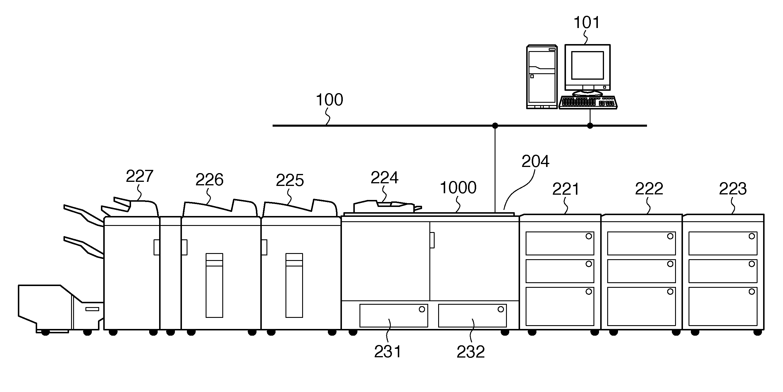
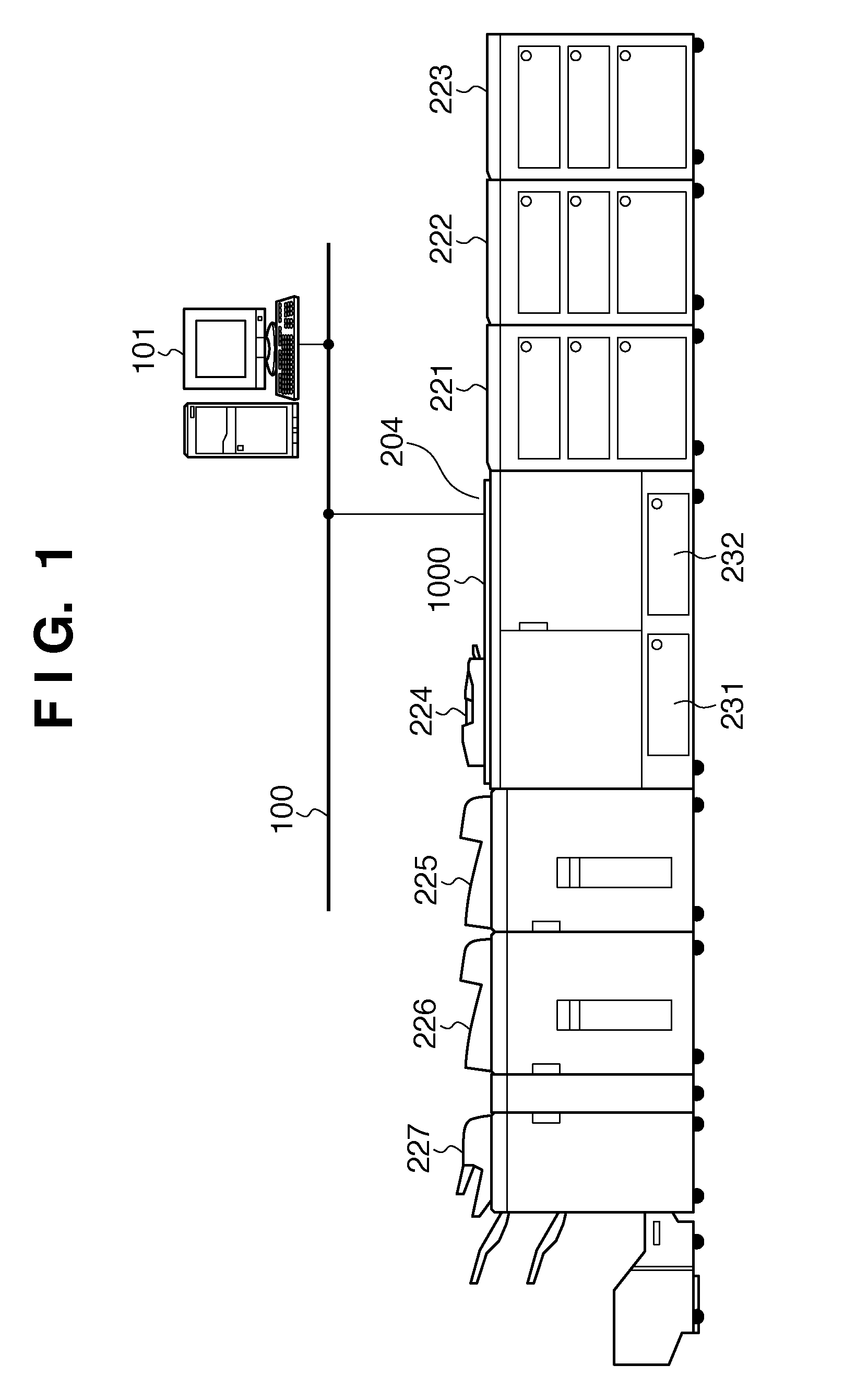
[0040]FIG. 1 depicts a view illustrating the configuration of a printing (POD) system according to an embodiment of the present invention. In this system, apparatuses having a plurality of different roles are connected to each other, and thus it is possible to perform complicated sheet processing (such as bookbinding, folding, or punching) on paper that has been printed.

[0041]A digital printing device 1000 prints images using a recording agent such as a toner on media (a sheet) based on image data. Below is a simple description of print processing when the digital printing device 1000 is a print apparatus employing an electrophotographic method. A semiconductor laser is driven by a signal modulated according to image data to emit laser light, and this laser light is reflected by a multi-sided mirror (such as a polygonal mirror) and irradiated onto a uniformly charged photosensitive drum. Thus, a latent image corresponding to the image data is formed on the photosensitive drum, and t...

second embodiment

[0104]In the above first embodiment, an example is described in which the digital printing device 1000 performs processing to adjust the scaling of the image to undergo composition relative to the image to be composited. However, a configuration may also be adopted in which scaling modification processing for matching the scalings to prevent misregistration when printing is performed by the computer 101.

[0105]Specifically, a configuration is acceptable in which when performing the data conversion processing in step S3 in FIG. 16, that is, when producing PDL data, data conversion processing is executed in consideration of the scaling setting that was modified in step S27 in FIG. 18.

[0106]Also, the above first embodiment describes modifying the scaling of the image to undergo composition, which will be composited with the clear color offset plate. A configuration may also be adopted in which, for example, scaling is modified for the image data of the image to be composited, that is, t...

third embodiment

[0111]In the above embodiments, when the scaling of the image to be composited is not the same as the scaling of the image to undergo composition, this fact is detected, and correction is performed such that those scalings become the same. In the third embodiment, although detection of whether or not those scalings are the same is performed, correction processing is not performed.

[0112]FIG. 23 depicts a view illustrating an example of a screen that corresponds to FIG. 14 according to the above first embodiment. This screen differs from the screen in FIG. 14 in that here, there is no radio button 1402 for automatic setting of scaling when scaling is not the same.

[0113]FIG. 24 depicts a view illustrating an example of a screen displayed immediately after identifying that the scaling of the image to be composited and the scaling of the image to undergo composition are not the same, when clear image data to be composited has been selected in the screen shown in FIG. 23.

[0114]Here, becau...


PUM


Abstract

When a combining instruction for combining first image data with second image data being stored in a print apparatus is accepted, a processing parameter that has been set for the second image data to be combined with the first image data is obtained, and a determination is made of whether or not an image area of the first image data and an image area of the second image data match if the first image data and the second image data are overlaid, based on the processing parameter, and when determined that the image area of the first image data and the image area of the second image data do not match, the first image data is modified, and that modified first image data is transmitted to the print apparatus.

Description

BACKGROUND OF THE INVENTION[0001]1. Field of the Invention[0002]The present invention relates to a print apparatus and a print control apparatus that receive and print a print job from an external device, and an image processing apparatus.[0003]2. Description of the Related Art[0004]The market is expanding for Print On Demand (POD), in which a digital printing device is used instead of a conventional offset printing device widely used in commercial printing. In view of such circumstances, manufacturers of office equipment and the like are investigating new entry into the POD market, which is a new field. In particular, recently, for example, there has been ongoing investigation of print apparatuses and printing systems adapted to not only an office environment, but also to a POD environment where different use cases and needs than for an office environment are assumed. For example, a printing system is sought that utilizes a benefit that it is possible to produce only a necessary am...

Claims


Application Information

Patent Timeline
Patent Type & Authority Applications(United States)
IPC IPC(8): G06K15/00
CPCG06K15/1809G06K15/1819G06K15/1889G06K15/1825G06K15/1822
Inventor KANAMOTO, YOSHIJI
Owner CANON KK
Why Eureka
Try Eureka