
LED light module for use in a lighting assembly

a technology of led light and lighting assembly, which is applied in the direction of lighting and heating apparatus, semiconductor devices for light sources, coupling device connections, etc., can solve the problems of poor luminous efficacy, inconvenient use, and inconvenient use of incandescent bulbs, and achieves poor luminous efficacy. , the effect of reducing the number of lamps

Inactive Publication Date: 2011-03-17
KORRUS INC
View PDF100 Cites 100 Cited by
  • Summary
  • Abstract
  • Description
  • Claims
  • Application Information

AI Technical Summary

Benefits of technology

[0012]In accordance with one embodiment, an LED light module removably coupleable to a receiving lighting assembly is provided. The LED light module comprises an LED lighting element. A thermal interface member is coupled to the LED lighting element and is configured to resiliently contact one or more thermally conductive surfaces of a receiving lighting assembly when the LED light module is installed in the receiving lighting assembly, the thermal interface member configured to thermally couple the LED lighting element of the LED light module to at least one of the one or more thermally conductive surfaces of the receiving lighting assembly. The LED light module also comprises one or more resilient members configured to generate a compression force when the LED light module is installed in the receiving lighting assembly to maintain a compressive contact force between the thermal interface member of the LED light module and at least one of the one or more thermally conductive surfaces of the receiving lighting assembly. The LED light module further comprises one or more electrical contact members of the LED light module configured to releasably contact one or more electrical contact elements of a socket of the receiving lighting assembly when the LED light module is installed in the lighting assembly. The LED light module electrical contact members are configured such that they will establish an operative electrical connection with the socket whose mating contacts are protected from inadvertent human contact.
[0013]In accordance with another embodiment, a lighting assembly is provided, comprising a heat dissipating member and a socket attachable to the heat dissipating member, said socket comprising a plurality of electrical contact elements disposed behind openings in a surface of the socket. The lighting assembly also comprises an LED light module removably coupleable to the socket of the heat dissipating member, comprising an LED lighting element and a thermal interface member coupled to the LED lighting element. The thermal interface member is configured to resiliently contact one or more thermally conductive surfaces of the heat dissipating member when the LED light module is coupled to the socket to establish a thermal path between the LED lighting element and the heat dissipating member. The LED light module also comprises one or more resilient members configured to compress when the LED light module is coupled to the socket to generate a compression force between the thermal interface member and at least a portion or an element of the heat dissipating member. The LED light module further comprises one or more electrical contact members of the LED light module configured to releasably contact one or more electrical contact elements of the socket when the LED light module is installed in the lighting assembly. The LED light module electrical contact members are configured such that they will establish an operative electrical connection with the socket whose mating contacts are protected from inadvertent human contact.
[0014]In accordance with another embodiment, a method for coupling an LED light module to a socket, the socket coupleable to a lighting assembly, is provided. The method comprises axially advancing at least a portion of the LED light module at least partially into the socket, the LED light module comprising an LED lighting element coupled to a thermal interface member, the LED light module further comprising one or more resilient members operatively coupled to the thermal interface member. The method also comprises rotating the LED light module relative to the socket, wherein at least one of said axial and rotational movements of the LED light module brings one or more electrical contact members of the LED light module into contact with one or more electrical contact elements of the socket, said LED light module electrical contact members configured such that they will establish an operative electrical connection with the socket whose mating contacts are protected from inadvertent human contact.

Problems solved by technology

However, it is often difficult to combine both form and function into a lighting assembly without compromising one or the other.
Incandescent bulbs, while inexpensive, are not energy efficient, and have a poor luminous efficacy.
Fluorescent bulbs and HID bulbs require a ballast to regulate the flow of power through the bulb, and thus can be difficult to incorporate into a standard lighting assembly.
Moreover, LEDs generally fail by a gradual dimming over time, rather than abruptly burning out, as do incandescent, fluorescent, and HID bulbs.
While LEDs have various advantages over incandescent, fluorescent, and HID bulbs, the widespread adoption of LEDs has been hindered by the challenge of how to properly manage and disperse the heat that LEDs emit.
The performance of an LED often depends on the ambient temperature of the operating environment, such that operating an LED in an environment having a moderately high ambient temperature can result in overheating the LED and premature failure of the LED.
Moreover, operation of an LED for an extended period of time at an intensity sufficient to fully illuminate an area may also cause an LED to overheat and prematurely fail.
This often results in the creation of an LED sub-assembly that is not upgradeable or replaceable within a given lighting assembly.
Additionally, conventional LED light assemblies that are removable generally engage a lighting assembly with exposed electrical contacts, which can be inadvertently touched by a user.
Such exposed electrical contacts can pose a safety risk to users where the voltage provided to the LED assembly is high (e.g., 110V line voltage).

Method used


Image

  • LED light module for use in a lighting assembly
  • LED light module for use in a lighting assembly
  • LED light module for use in a lighting assembly

Examples


Embodiment Construction

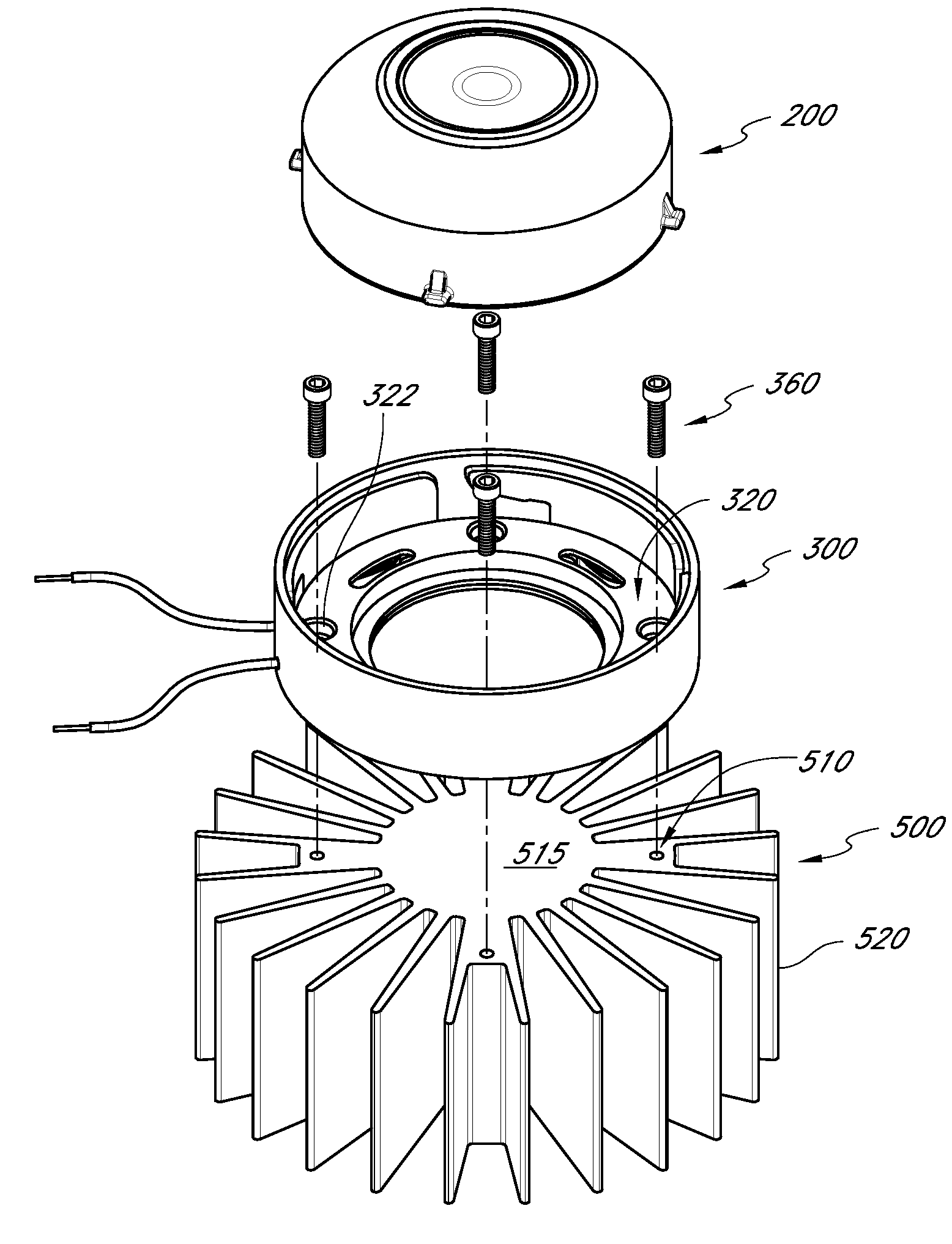
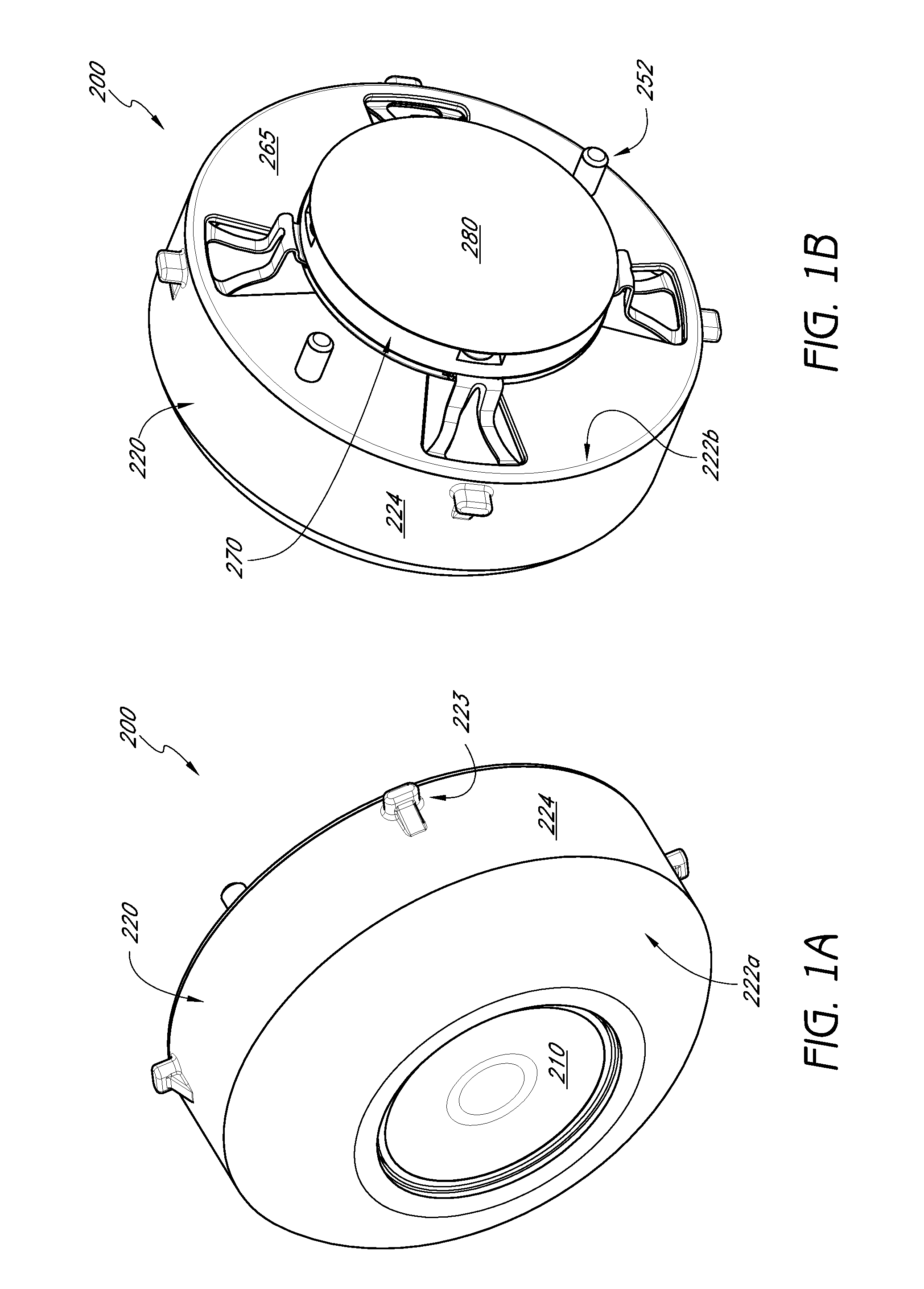
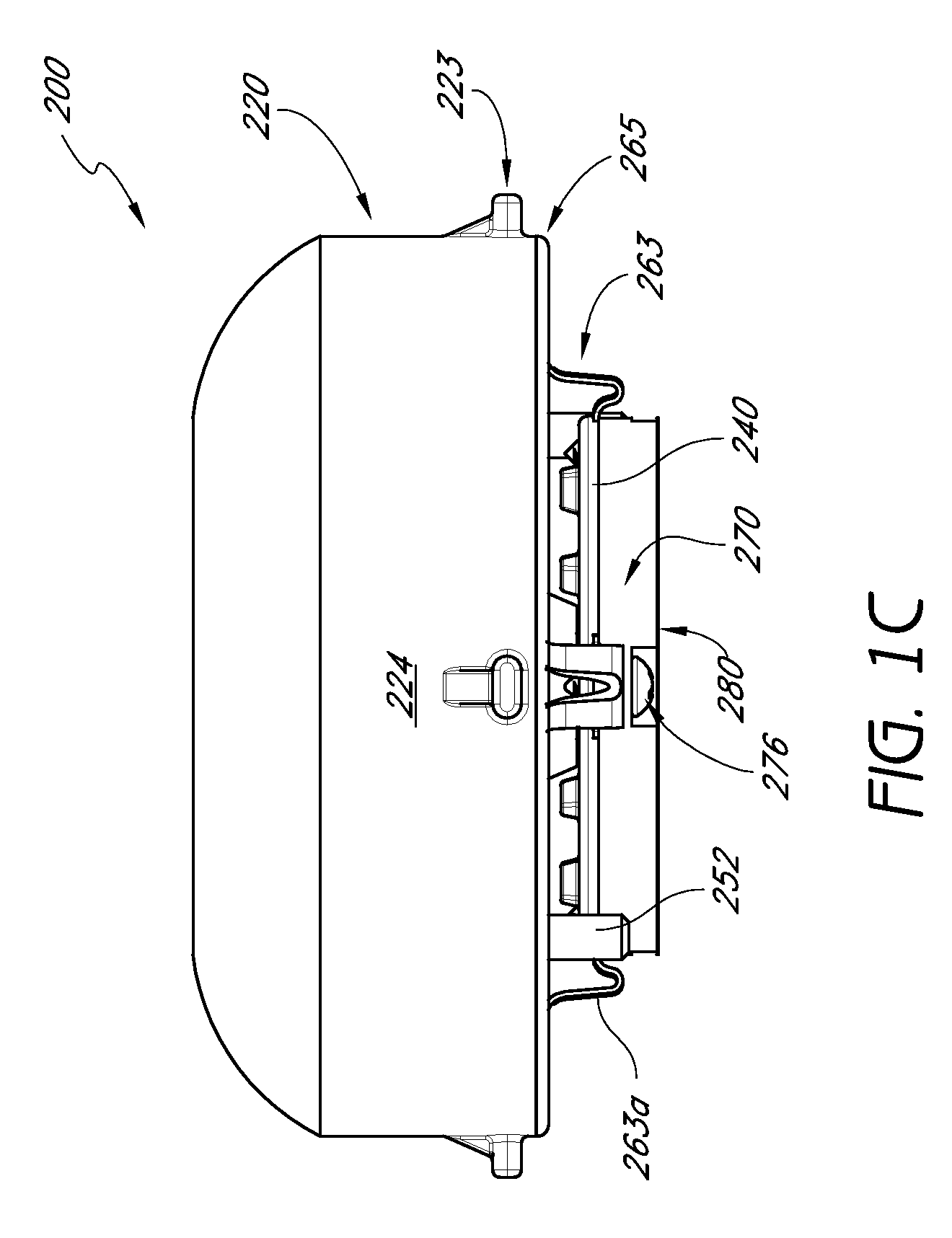
[0050]FIGS. 1A-3B show one embodiment of an LED light module 200. The LED light module assembly 200 can include an optic 210; a housing 220; an optic retainer 230; an LED driver printed circuit board (PCB) 250; a lighting element, such as an LED 290; a lower retaining member 240, a resilient member 260, an upper retaining member 265, a thermal interface member 270; and a thermal pad 280.

[0051]The housing 220 can include an opening 221 (see FIG. 2A) sized to receive the optic 210 at least partially therein, which can be removably fixed to the housing 220 by the optic retainer 230 such that a rim or shoulder 210a of the optic 210 is disposed against an underside surface 220a of shoulder 220b (see FIG. 2B-3B) of the opening 221. The optic retainer 230 can have an opening 232 through which at least a portion of the optic 210 can extend. The optic retainer 230 can also have a recessed annular shelf 233 that the shoulder 210a of the optic 210 abuts against. In the illustrated embodiment, ...


PUM


Abstract

A removable LED light module for use in a lighting assembly includes an LED lighting element and one or more resilient members to maintain a compression force between the LED light module and a socket and / or heat dissipating member or thermally conductive housing to provide effective heat transfer from the LED to the heat dissipating member or thermally conductive housing. One or more electrical contact members of the LED light module is configured to releasably contact one or more electrical contact elements of a socket of the lighting assembly when the LED light module is coupled to the socket to establish an electrical connection between the LED light module and the socket, said electrical contact elements positioned behind openings in a surface of the socket to partially obstruct access to said electrical contact elements.

Description

CROSS-REFERENCE TO RELATED APPLICATIONS[0001]This application claims the benefit of U.S. Provisional Patent Applications No. 61 / 233,327 filed Aug. 12, 2009 and 61 / 361,273 filed Jul. 2, 2010, the entire contents of both of which are incorporated herein by reference and should be considered a part of this specification.BACKGROUND[0002]1. Field[0003]The present invention is directed to an LED light module that can be removably coupled thermally and electrically to a heat sink or lighting assembly.[0004]2. Description of the Related Art[0005]Lighting assemblies such as ceiling lights, recessed lights, and track lights are important fixtures in many homes and places of business. Such assemblies are used not only to illuminate an area, but often also to serve as a part of the decor of the area. However, it is often difficult to combine both form and function into a lighting assembly without compromising one or the other.[0006]Traditional lighting assemblies typically use incandescent bulb...

Claims


Application Information

Patent Timeline
IPC IPC(8): F21V29/00H01J61/52
CPCF21S48/328F21V19/001F21V19/045F21V29/004F21K9/30F21V29/22F21V29/70F21V29/773F21Y2101/02F21K9/20F21Y2115/10F21V19/04
Inventor ALEXANDER, CLAYTONMUNDELL, BRANDON S.RIPPEY, III, ROBERT
Owner KORRUS INC
Learn More