
Fixing device and image forming apparatus incorporating the fixing device

a fixing device and fixing device technology, applied in the direction of electrographic process apparatus, instruments, optics, etc., can solve the problems of uneven surface layer thickness, edge marks, etc., and achieve the effect of reducing thickness, increasing thickness, and reducing thickness

Inactive Publication Date: 2011-03-17
RICOH KK
View PDF71 Cites 106 Cited by
  • Summary
  • Abstract
  • Description
  • Claims
  • Application Information

AI Technical Summary

Benefits of technology

[0013]In yet another aspect, the elastic layer includes at least one pair of regions of increased thickness where edges of at least one prescribed size of the transfer sheet pass through.
[0014]In yet another aspect, one of a metal core and a substrate includes regions of reduced thickness where at least one prescribed size of the transfer sheet pass through. The regions of increased thickness are increased by the same amount by which the regions of the reduced thickness of the one of a metal core and a substrate are reduced in thickness.

Problems solved by technology

Thus, in a conventional fixing device, when small size transfer sheets are repeatedly or normal size transfer sheets are longitudinally conveyed, portions of the surface layer at edges of the transfer sheet become rough and thereby edge marks are created.
Further, although it does not improve the surface roughness created by passage of the transfer sheet, JP-2006-154540-A employs a cleaning roller in a fixing device to contact and erase contact marks on the surface of a fixing belt created by a contact-type temperature probe contacting the fixing belt.
However, with this technology, when transfer sheets of a small size are repeatedly conveyed or normal size transfer sheets are longitudinally conveyed, portions on the surface of a fixing member or a pressure member corresponding to edges of the transfer sheet are roughened and lines drawn thereat, creating lines in images on large size transfer sheets as a problem to be resolved.
The above-mentioned problem occurs in a nip created by the fixing member and the pressure member pressing into each other on their surfaces where edges of a transfer sheet pass through due to concentration of stress thereat, induced in proportion to a thickness of the transfer sheet.
Consequently, when a fixing belt or sleeve having an elastic surface layer on a metal substrate is employed and a thick transfer sheet is conveyed through the nip, the substrate of the fixing belt or sleeve is likely to be either deformed or damaged due to the concentration of stress on the positions corresponding to edges of the transfer sheet, producing an abnormal image.

Method used


Image

  • Fixing device and image forming apparatus incorporating the fixing device
  • Fixing device and image forming apparatus incorporating the fixing device
  • Fixing device and image forming apparatus incorporating the fixing device

Examples


Embodiment Construction

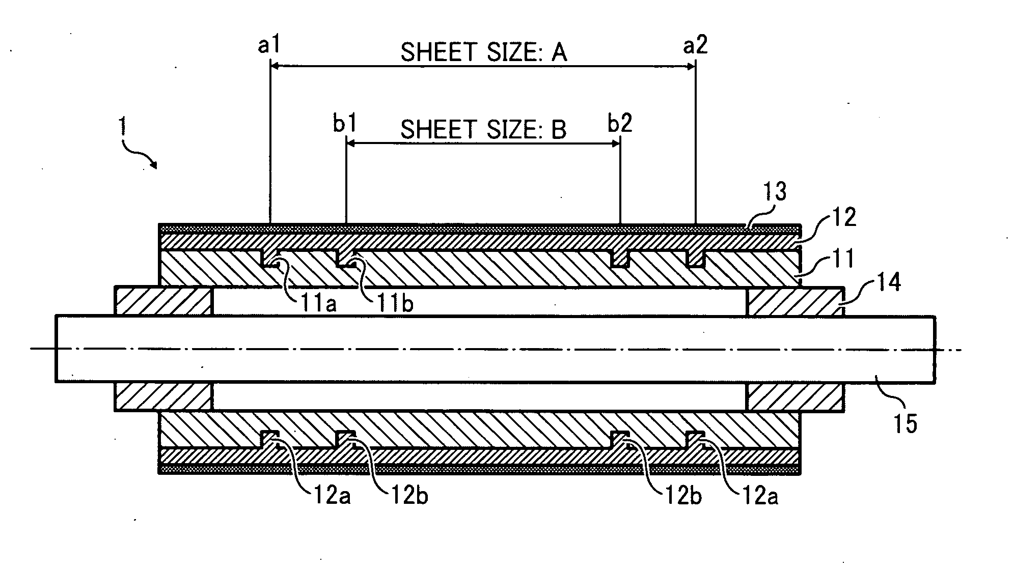
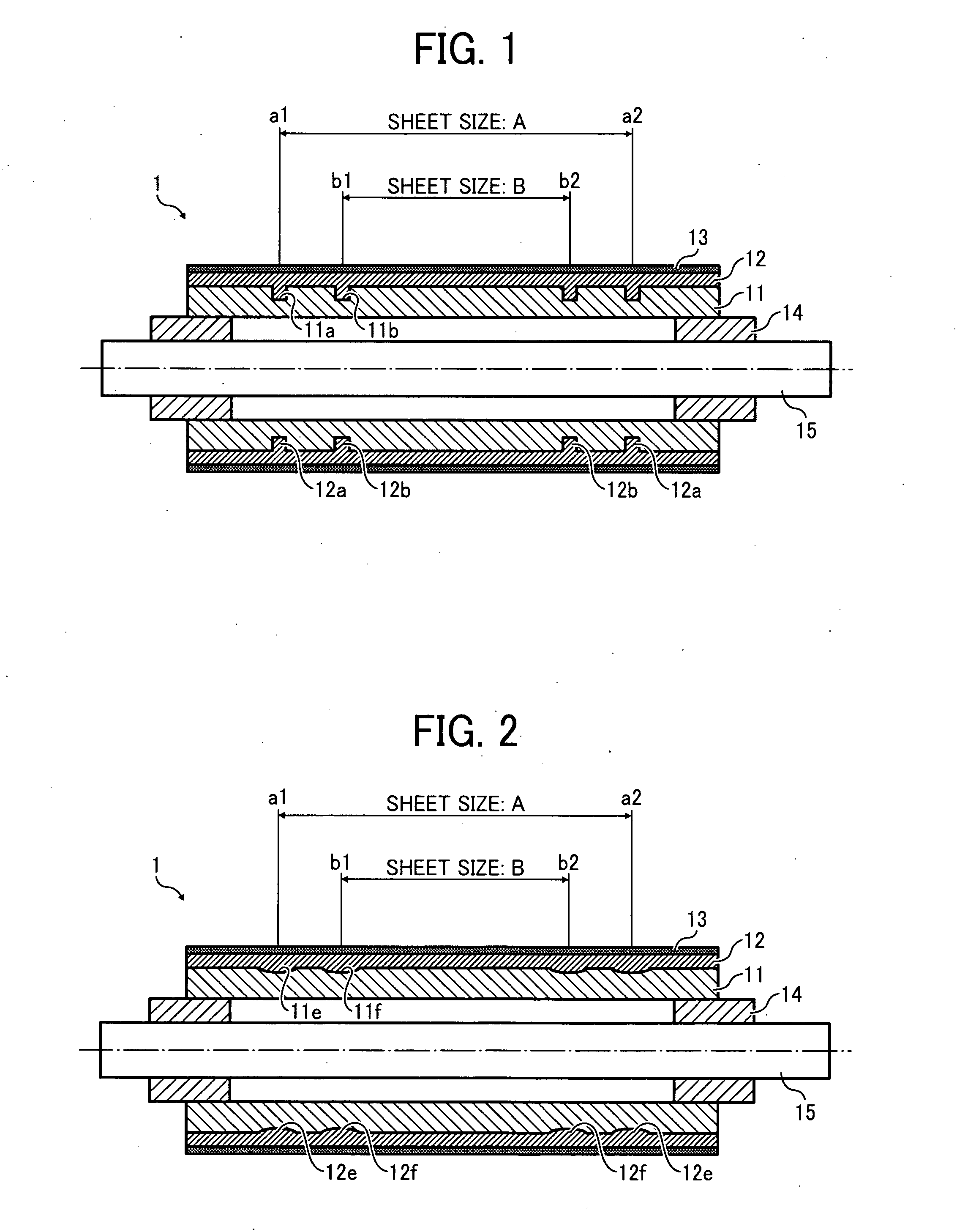
[0029]Referring now to the drawings, wherein like reference numerals and marks designate identical or corresponding parts throughout several figures, in particular in FIG. 1, a fixing device is described. As shown, a fixing device of the present invention includes a fixing member and a pressure member. One of the fixing member and the pressure member includes a metal core or a substrate and an elastic layer on a front side thereof, so that they press into each other and form a nip therebetween. Then, by conveying a transfer sheet having a toner image transferred thereon through the nip, the toner image is fixed thereonto.

[0030]Now, an exemplary pressure member is described with reference to FIGS. 1 and 2. The pressure device employed in the fixing device is generally called a pressure roller.

[0031]The pressure roller includes a cylindrical metal core 11 as a substrate, an elastic layer 12, such as silicon rubber, etc., overlying the front surface of the metal core 11, and a releasin...


PUM


Abstract

An elastic layer is provided on a surface of one of a metal core and a substrate. A fixing member and a pressure member press into each other and collectively create a nip therebetween. A toner image is conveyed and fixed when passing through the nip. A thickness of the elastic layer is different in at least two widthwise regions by the same amount from the other region. A pair of edges of a prescribed size of the transfer sheet pass through these two widthwise regions, respectively.

Description

CROSS-REFERENCE TO RELATED APPLICATIONS[0001]This application claims priority pursuant to 35 USC §119 to Japanese Patent Application No. 2009-211204, filed on Sep. 14, 2009, the entire contents of which are herein incorporated by reference.BACKGROUND OF THE INVENTION[0002]1. Field of the Invention[0003]The present invention relates to an image forming apparatus, such as a printer, a copier, a facsimile machine, a multi functional machine including functions of the printer and an image reading device, etc., and in particular, to a fixing device provided in the image forming apparatus.[0004]2. Discussion of the Background Art[0005]An image forming apparatus employing an electro-photographic system generally includes a drum or belt type photoconductive member as an image bearer, a charge device, and an exposure device, each arranged around the photoconductive member. The image forming apparatus further includes a developing device, a cleaning device, and a charge-removing device, also ...

Claims


Application Information

Patent Timeline
Patent Type & Authority Applications(United States)
IPC IPC(8): G03G15/20
CPCG03G2215/2048G03G15/206G03G15/2053
Inventor IMADA, TAKAHIROEHARA, MASANAOOGAWA, TADASHIUENO, SATOSHISEO, HIROSHIHASE, TAKAMASAISHI, KENJI
Owner RICOH KK
Features
  • Generate Ideas
  • Intellectual Property
  • Life Sciences
  • Materials
  • Tech Scout
  • Unparalleled Data Quality
  • Higher Quality Content
  • 60% Fewer Hallucinations
Learn More