
Diver operated jetting sled and method

Inactive Publication Date: 2011-03-17
TRITON DIVING SERVICES
View PDF15 Cites 5 Cited by
  • Summary
  • Abstract
  • Description
  • Claims
  • Application Information

AI Technical Summary

Benefits of technology

[0004]The present invention overcomes the inherent drawbacks of previous jetting sleds or trenching machines by providing a relatively small jetting sled, self propelled and manually operable by a diver positioned on a small platform at the rear of the jetting sled. The diver operates hydraulic levers to move the jetting sled forward and backward while a pipeline is being buried on the bottom of the ocean floor, thus insuring that no damage will occur to the pipelines and crossings in a congested field. Jetting water, compressed air and hydraulic power will be provided to the jetting sled from a surface vessel through a hose bundle.
[0005]In order to prevent damage to the pipeline being buried, the jetting sled will have guides just below driving rollers to help set the jetting sled over the pipeline.
[0006]The inventive jetting sled has buoyancy tanks mounted on each side for the purpose of floating / jumping crossings. As further noted below, the buoyancy tanks will assist the diver in jumping the jetting sled over an intersecting pipeline without the assistance of a crane. This is another feature that will save time and will eliminate the need to have a crane on a barge or other vessel pick up the jetting sled at each crossing in a field of multiple pipeline crossings.
[0013]With diver operation, there is no danger of damage to pipeline crossings because with a diver operated sled as soon as contact is made with a crossing pipeline, the sled is stopped by the diver on board the jetting sled. Another advantage to the inventive jetting sled over others is that it can jump over crossings without the need of a crane. A crane is only needed for the first installation and the final removal. All crossings can be jumped by the jetting sled on it's own with no need for a crane.

Problems solved by technology

This gives rise to a potentially hazardous situation in that the jetting sled or trenching machine could damage or rupture a buried pipeline crossing the path of the pipeline being installed.
When such a device is remotely operated, the chances for a mishap increase because the operator does not have direct contact with the jetting sled or trenching machine.
Any feed back to the operator, whether hydraulic or electronic may be too late to prevent an accident.
Visual monitoring by TV may be obscured by silt.

Method used


Image

  • Diver operated jetting sled and method
  • Diver operated jetting sled and method
  • Diver operated jetting sled and method

Examples


Embodiment Construction

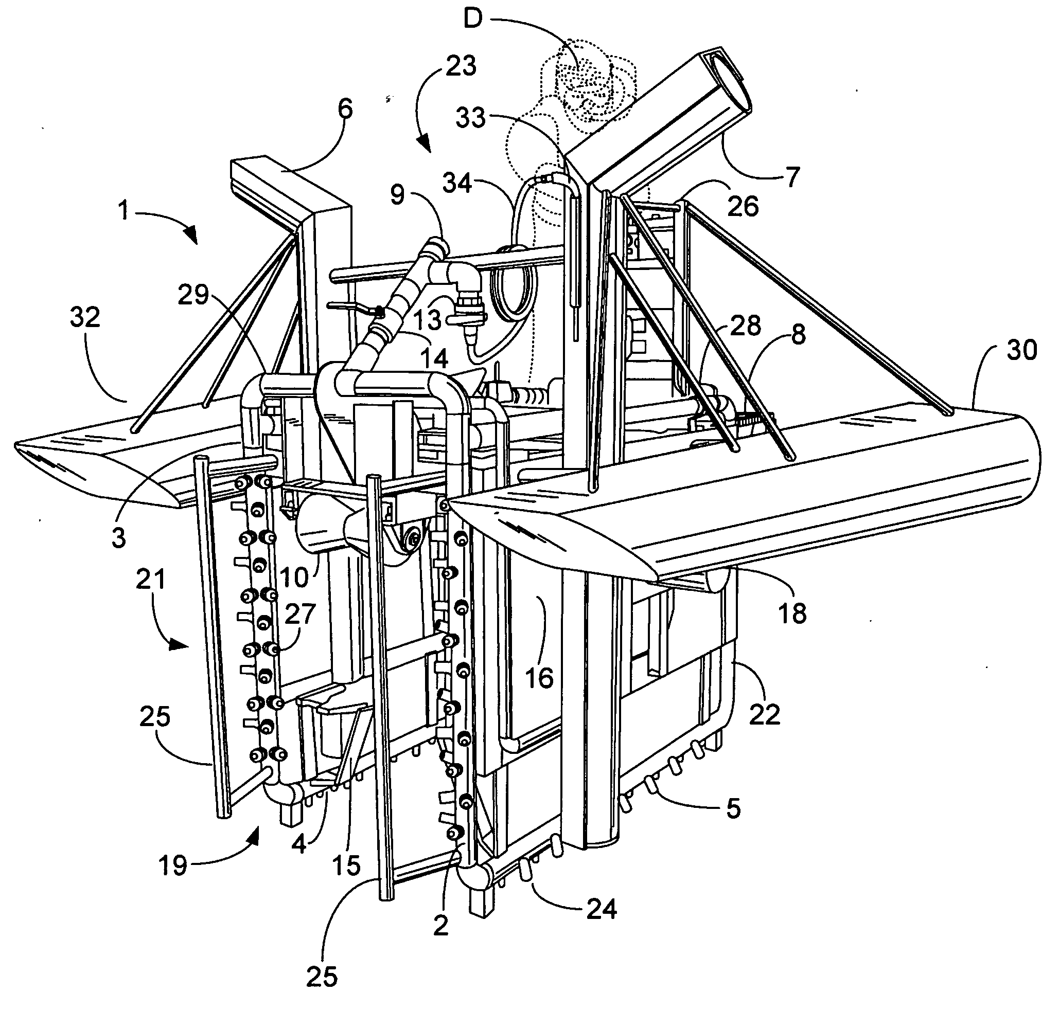
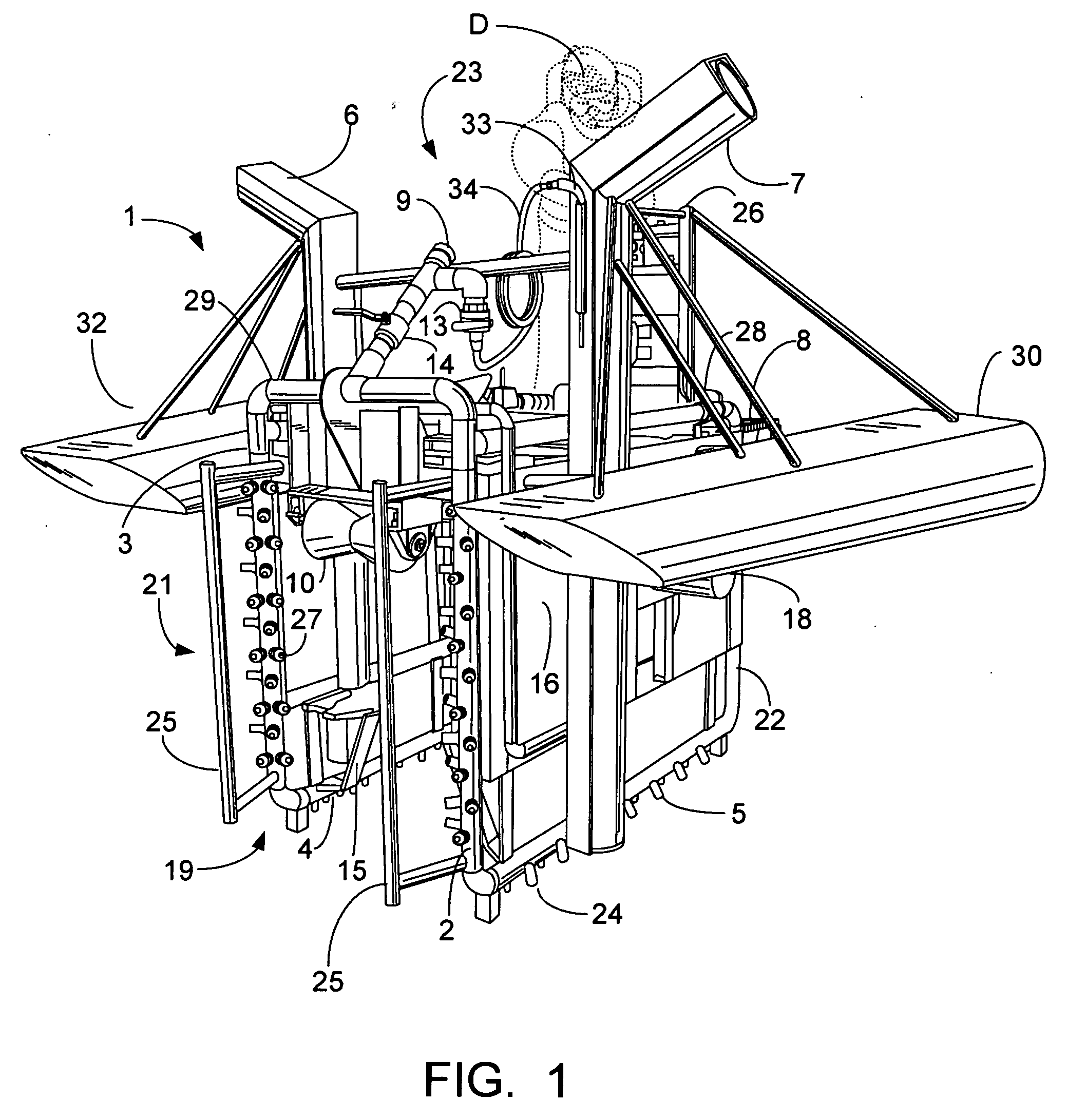
[0032]As depicted in FIG. 1, the inventive jetting sled 1 is meant to ride atop a pipeline, not shown, and jet a ditch below and around the pipeline while moving along the pipeline. A cross section of the jetting sled 1 would resemble an inverted “U”. The jetting sled 1 has a front end 19, a rear end 20, a left side 22, a right side 21, an upper side 23 and a bottom side 24. At the front end 19 can be seen one of the upper rollers 10 that would ride on the top of the pipeline. The guides 15 assist in placing the jetting sled 1 on the pipeline.

[0033]Also shown at the front end 19 are two vertical bumpers 25, one on the left side 22 and one on the right side 21. The bumpers 25 are meant to make contact with any intersecting or crossing pipelines and alert the diver operating the jetting sled to initiate crossing procedures.

[0034]As further depicted in FIG. 1, there is a left vertical jetting head 2 and a right vertical jetting head 3, as well as a right horizontal jetting head 4 and a...


PUM


Abstract

A light weight self propelled jetting sled operable by a diver used to bury pipelines below the ocean floor with vertical jetting heads, horizontal jetting heads, bumpers, air lifts, buoyancy chambers, adjustable power rollers, upper rollers, water hand jet, and a control panel. In the method, with the use of buoyancy tanks and a jump sling, the diver can jump the jetting sled over crossing pipelines and continue the jetting operation without the need for surface cranes

Description

[0001]The present invention relates to an underwater device and method for burying pipelines at the bottom of a body of water. More particularly, the present invention relates to a diver operated jetting sled used to bury pipelines below the ocean floor for cover from storms that may move the pipelines or shrimp nets or trawls that could snag and cause damage to the pipelines.BACKGROUND OF THE INVENTION[0002]In the past jetting sleds or trenching machines were fabricated to bury pipelines down below the natural bottom of bodies of water such as the Gulf of Mexico and others. Some of these earlier jetting machines in the past were pulled by an air tugger or winch positioned on a barge or other vessel. Other large to medium size jetting machines were self propelled, being powered by a set of wheels powered by hydraulic motors and operated by a technician positioned on a barge or vessel. These larger jetting machines had to be installed over the pipeline with the use of a crane or an “...

Claims


Application Information

Patent Timeline
IPC IPC(8): F16L1/12
CPCE02F3/8866F16L1/16E02F3/9206
Inventor HAZEN, FRANK
Owner TRITON DIVING SERVICES
Learn More