Arc surface grinding device

Inactive Publication Date: 2011-03-17
HON HAI PRECISION IND CO LTD
View PDF7 Cites 18 Cited by
  • Summary
  • Abstract
  • Description
  • Claims
  • Application Information

AI Technical Summary

Problems solved by technology

However, the large size bed r

Method used


Image

  • Arc surface grinding device
  • Arc surface grinding device
  • Arc surface grinding device

Examples


Embodiment Construction

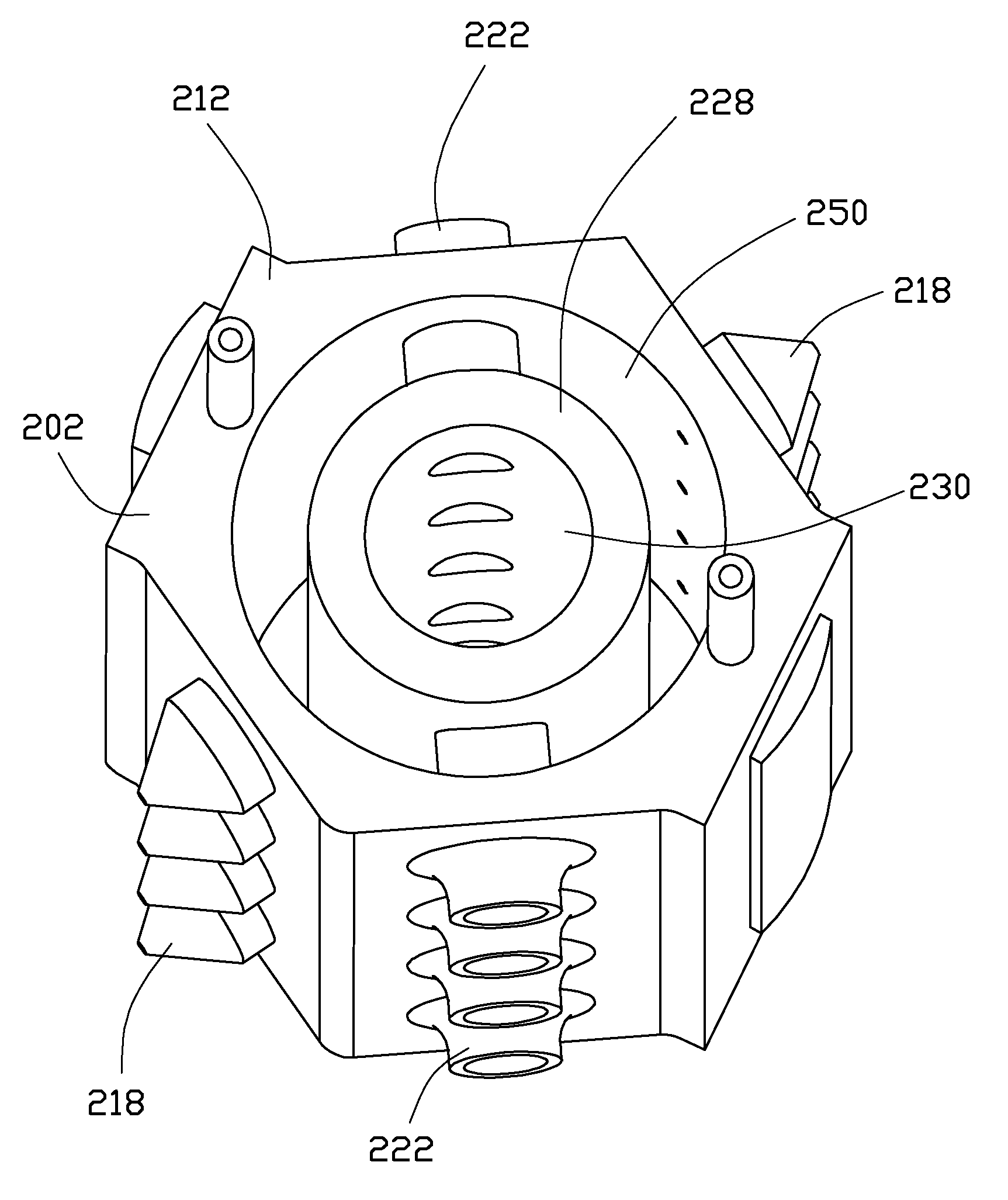
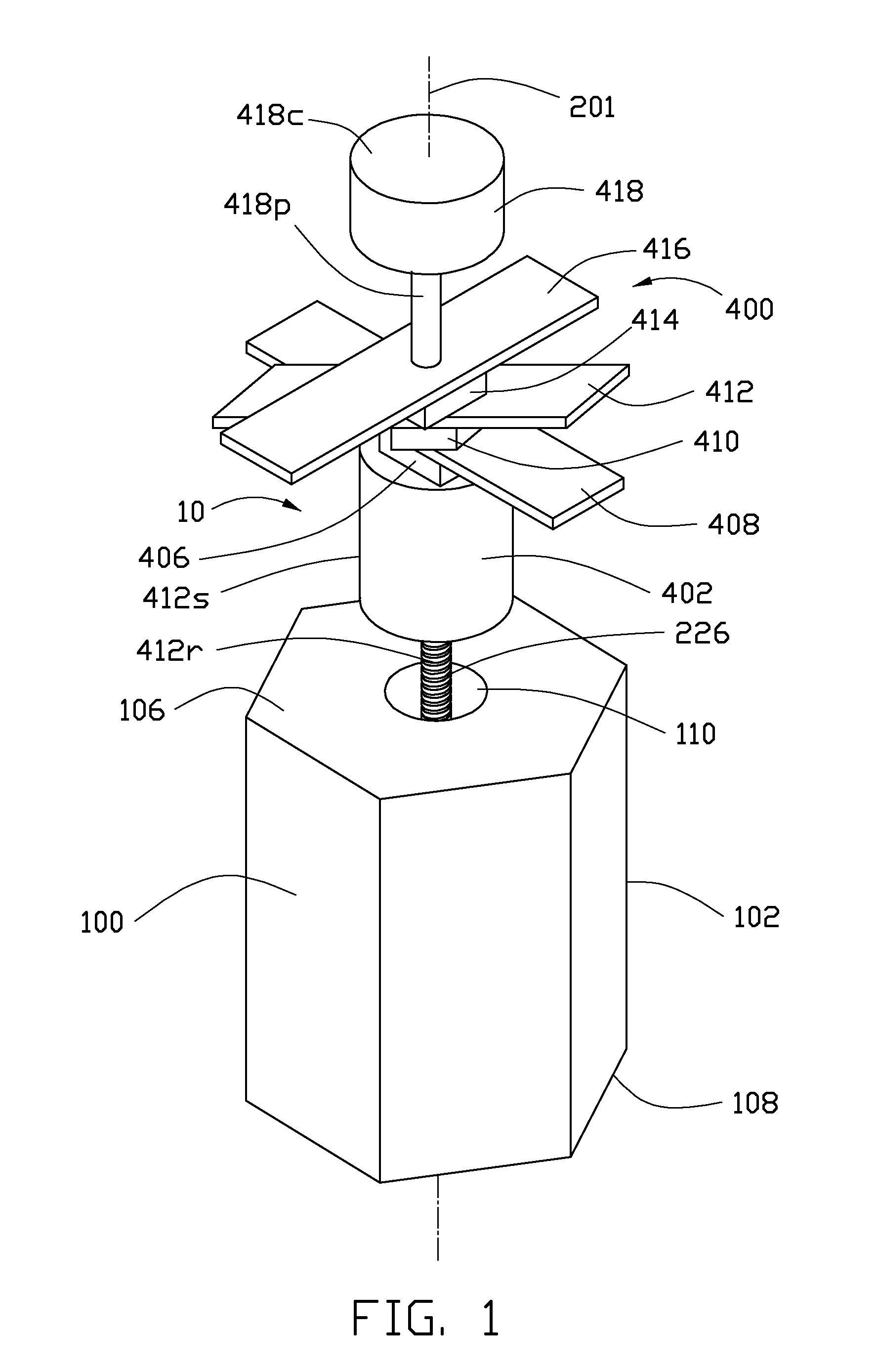
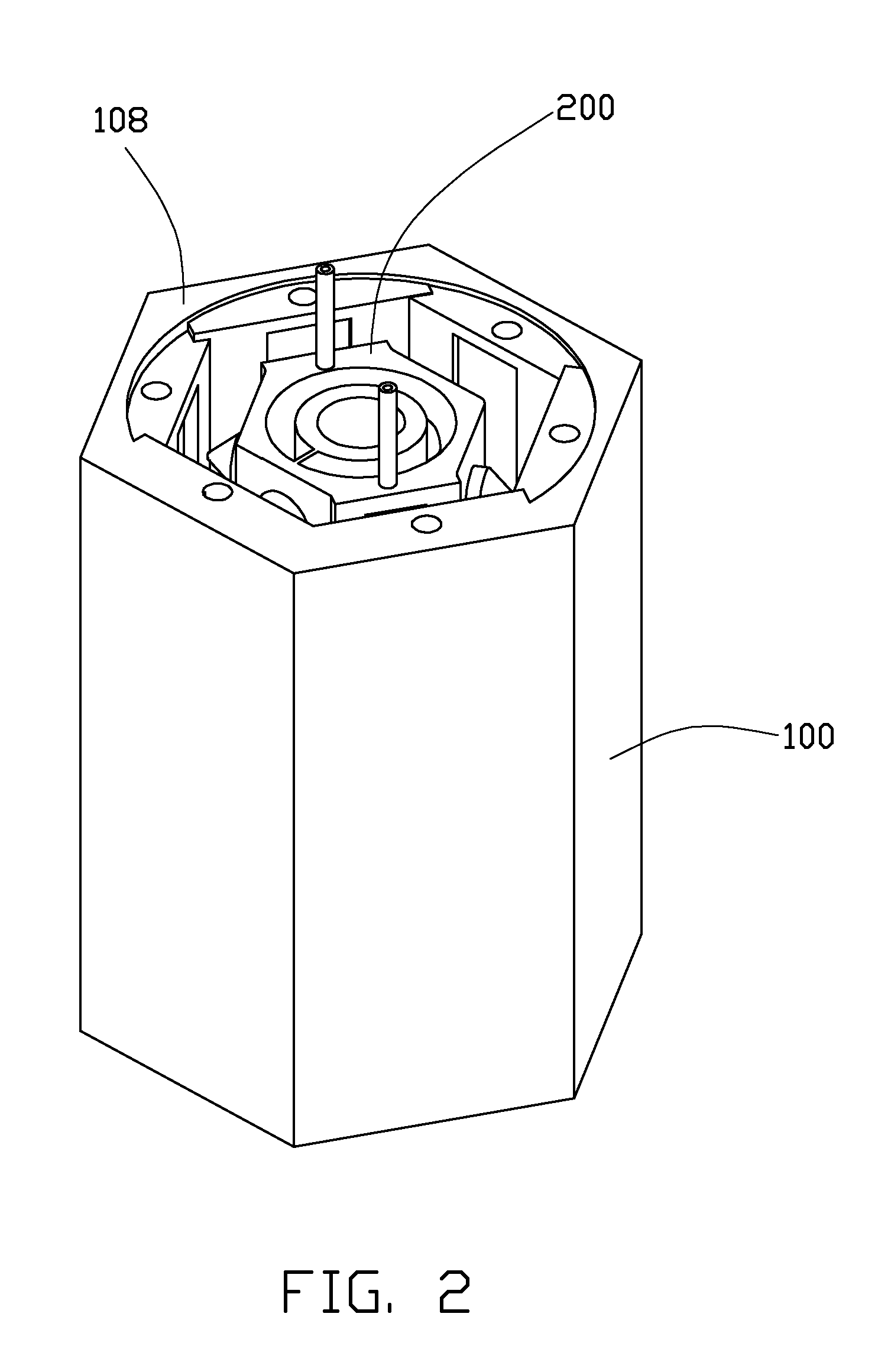
Referring to FIGS. 1-2, a grinding device 10, according to an exemplary embodiment, is configured for grinding a number of workpieces (not shown) at the same time whereby a surface of each of the workpieces is grinded into a desired arc surface. The grinding device 10 includes a fixed barrel 100, a moving barrel 200, a number of grinding plates 300 (see FIG. 4), and an actuator 400.

Referring to FIGS. 1 and 3, the fixed barrel 100 includes a first main body 102 which is generally a hexagonal prism in shape and is generally symmetrical about a central axis 201 of the fixed barrel 100. The first main body 102 includes a top plate 106 and a bottom plate 108.

The first main body 102 defines a hexagonal prism chamber 104 therein which is symmetrical about the central axis 201. The hexagonal prism chamber 104 passes through the bottom plate 108 and is bounded by six inner side surfaces 112 of the first main body 102. Each of the inner side surfaces 112 defines a holding groove 114 therein g...


PUM


Abstract

A grinding device includes a fixed barrel, a moving barrel, a grinding plate, and an actuator. The fixed barrel defines a chamber and includes a number of inner surfaces substantially parallel to a central axis, each of which defines a holding groove therein for holding a workpiece. The moving barrel is received in the chamber and includes a side surface substantially parallel to the central axis and defines an installation groove. The grinding plate is fixedly installed in the installation groove. The actuator is configured for driving the moving barrel to spin and move back and forth along the central axis, and driving the moving barrel to move towards a workpiece so that a surface of the workpiece is grinded into a desired arc surface by the grinding plate, and driving the moving barrel to move towards another workpiece after the desired arc surface of the workpiece is obtained.

Description

BACKGROUND1. Technical FieldThe present disclosure relates to grinding devices, and particularly, to an arc surface grinding device for grinding a number of workpieces at the same time whereby a surface of each of the workpieces is grinded into a desired arc surface.2. Description of Related ArtCurrent arc surface grinding devices generally include a bed with fixture for holding one or more workpieces and a grinding part for grinding the workpieces so that a surface of each of the workpieces is grinded into a desired arc surface. To increase efficiency, a large size bed is required to hold many workpieces at the same time. As such, the grinding part can be used to continuously grind the workpieces, or more grinding parts can be employed to grind the workpiece simultaneously. However, the large size bed reduces space usage efficiency.Therefore, it is desirable to provide a grinding device, which can overcome the above-mentioned problems.BRIEF DESCRIPTION OF THE DRAWINGSFIG. 1 is an i...

Claims


Application Information

Patent Timeline
IPC IPC(8): B24B1/00B24B27/00B24B41/06
CPCB24B19/26B24B55/12B24B41/06
Inventor PEI, SHAO-KAI
Owner HON HAI PRECISION IND CO LTD
Why Eureka
Try Eureka