External fixation component

a technology of fixing components and fixing parts, applied in the direction of rod connections, prostheses, invalid friendly devices, etc., can solve the problems of difficult cleaning, lack of versatility of use of plurality of different fixing members, etc., and achieve the effect of easy handling

Active Publication Date: 2011-03-17
STRYKER EURO OPERATIONS HLDG LLC
View PDF57 Cites 68 Cited by
  • Summary
  • Abstract
  • Description
  • Claims
  • Application Information

AI Technical Summary

Benefits of technology

[0011]It is an advantage of the fixation element according to the invention that after having clamped one pin or rod with one clamping assembly or capture member, a practitioner willing to attach subsequently a rod to a second clamping assembly of the element can freely turn, rotate and push said second clamping assembly in any direction in the 3D space without losing the first mentioned pin or rod pre-clamped in the first capture member. It is a further advantage that due to the spring actuated first and second clamping assemblies they can be handled easily without fixed clamping and maintain the rods in place. It is especially an advantage to use the clamps having the triangular structure according to this specification allowing accommodation of different rod diameter within a single capture member. The practitioner can check the robustness of his external fixator and if he finds that the rod he has used is not stiff enough, he simply opens the single clamping assembly containing said rod, removes said thinner rod, turns the clamping assembly by 120 degrees in one or the other direction around the longitudinal axis of said capture member and snaps and clamps a new thicker fixation rod replacing the original rod.

Problems solved by technology

The external fixation element according to the prior art provides a complicated rotation member which is directly connected to the capture members which element is difficult to clean and do not provide a versatile use with a plurality of different capture members.

Method used


Image

  • External fixation component
  • External fixation component
  • External fixation component

Examples


first embodiment

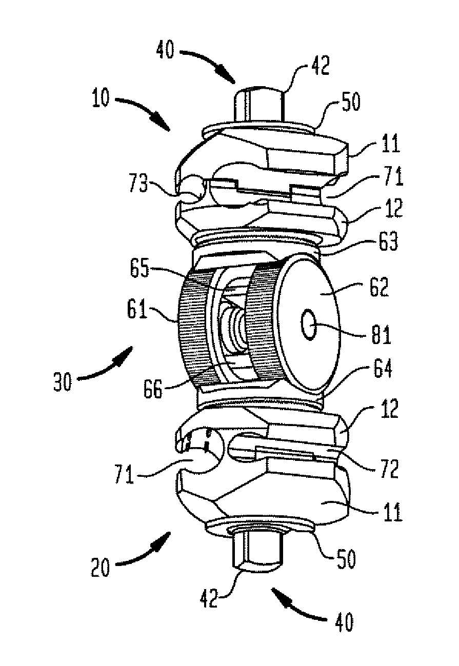
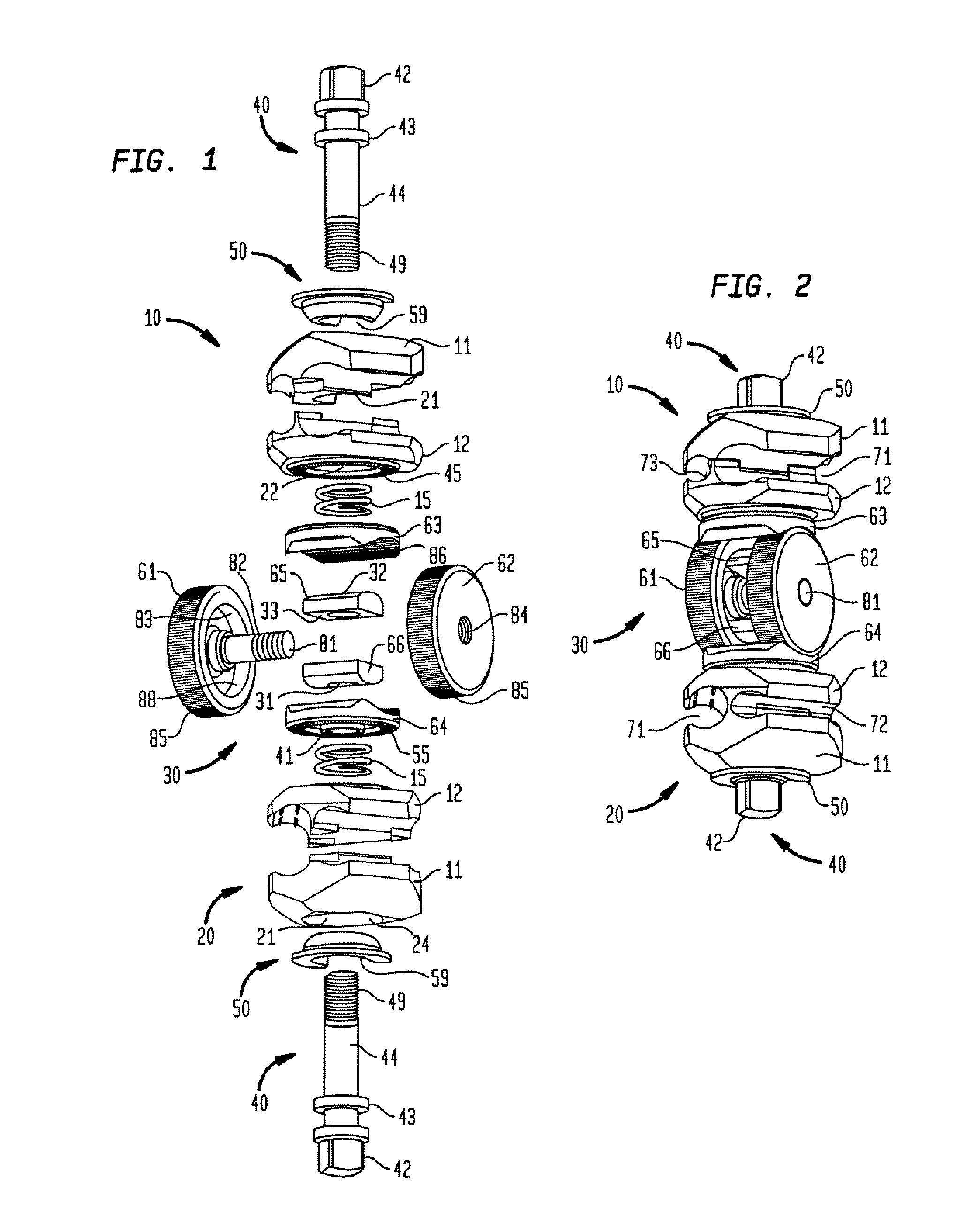
[0026]FIG. 1 shows an exploded view of the external fixation component of the present invention. The external fixation component comprises three elements. There is a first capture member 10 which is a clamping assembly. First capture member 10 is connected to a central rotation system 30 which is in turn connected to the second capture member 20, being a second clamping assembly. As will be seen in connection with FIGS. 8 and 9, different capture members can be used in connection with the central rotation member 30 as well as clamping assemblies from prior art if an adapted central locking screw and shaft is used.

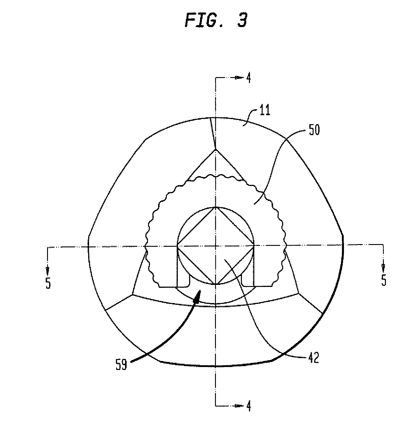
[0027]The first capture member 10 comprises a first jaw 11 and a second jaw 12 having central bores 21 and 22, respective. A screw 40 with a central shaft for locking the clamping assembly 10 is introduced through said bores 21 and 22. Shaft 40 enters the first jaw through a locking element 50 which is lodged in the rounded recess 24 of first jaw 11. The shaft 40 comprises ...

second embodiment

[0043]FIG. 8 shows a perspective view of a second embodiment according to the invention, wherein a further capture member 110 is provided. Said further capture member 110 is a multipin capture member having four reception openings 111 for pins. The openings 111 are provided as parallel grooves, but also oblique grooves are possible. Beside central screw 40 having the same function as in the first mentioned embodiment, there are two multipin fixation screws 112 to clamp jaws 11 and 12 of this embodiment. Lower jaw 12 comprises the anti-rotation interface surface 45 being in contact with blocking member 64 of the rotation member 30.

[0044]FIG. 9 shows a perspective view of a further different embodiment of the invention, showing a different additional capture member 120. Capture member 120 is provided with a plurality of pin grooves 121 between jaws 11 and 12, wherein the multipin clamp is closed using one central multipin fixation screw 122 as well as two lateral fixation screws 40. T...

fifth embodiment

[0045]FIG. 10 shows a perspective view of the invention, wherein FIGS. 11 and 12 show cross-sections of the embodiment according to FIG. 10. The external fixation element according to FIG. 10 comprises a first capture member 10 and a second capture member 20, wherein different clamping assemblies are used, providing three different receptions 71, 72 and 73 for rods or pins. The capture members 10, 20 are connected to the rotation member 130 via central shafts 40 traversing rotation blockers 63 and 64 comprising an anti rotation blocker surface 86. The central shafts 40 comprise an internal thread for accommodating counter screws 165 and 166, respectively. Heads of the counter screws 165 and 166 are lodged in the disc elements 161, 162, respectively.

[0046]The disc elements 161 and 162 are different to the discs 61 and 62, but have the common feature of a curved outer rolling surface 85 being opposite to anti rotation blocker surface 86 in blockers 63 and 64. The two discs 161 and 162...


PUM


Abstract

An external fixation component includes two capture members adapted to capture independently a first and a second element of an external fixation system. A rotation member is provided between the two capture members, coupled to both capture members such that the coupling allows the two capture members to rotate about three axes relative to each other. Each capture member comprises a central locking screw extending therethrough and defining a longitudinal axis of the associated capture member. The rotation member comprises two rotation blockers, each blocker providing one interface surface adapted to be in contact with a complementary interface surface of one of the capture members, each blocker further provides a surface opposite to the interface surface comprising an inner cylindrical surface. The rotation member comprises a central disc element forming a rolling surface as complementary surface to the inner cylindrical surface of the corresponding rotation blocker. The rotation member comprises two nuts, wherein each nut is associated to one locking screw of a corresponding capture member. Each locking screw of a capture member extends through the corresponding rotation blocker and engages the corresponding nut for an individual locking of each capture member.

Description

BACKGROUND OF THE INVENTION[0001]The present invention relates to an external fixation component comprising a first capture member adapted to capture a first element of an external fixation system and a second capture member adapted to capture a second element of an external fixation system; and a rotation member, coupled to the first capture member and to the second capture member such that the coupling allows the two capture members to rotate about three axes relative to each other.[0002]External fixation systems are widely used in orthopedics to connect two or more bone fragments to each other. Such orthopedic fixation systems comprise bone screws, pins, wires which are inserted directly into the bone material and these systems use external structural elements as fixation rods, bars and pin. In order to connect the rods and bars to form a rigid frame, different capture members and fixation clamps are used. Furthermore, fixation clamps are used to connect the screws and pins to th...

Claims


Application Information

Patent Timeline
Patent Type & Authority Applications(United States)
IPC IPC(8): A61B17/00
CPCA61B17/6466Y10T403/7105Y10T403/53Y10T403/71
Inventor MURNER, BEATWIDER, ROBERTTHOMKE, ROLAND
Owner STRYKER EURO OPERATIONS HLDG LLC
Why Eureka
Try Eureka