Fluid-directing multiport rotary valve

a rotary valve and multi-port technology, applied in the field of valves, can solve the problems of mechanical complexity, large capital expense, and deficiency of each current system, and achieve the effect of simple and accessibl

Inactive Publication Date: 2011-03-24
GULF SEA VENTURES
View PDF7 Cites 154 Cited by
  • Summary
  • Abstract
  • Description
  • Claims
  • Application Information

AI Technical Summary

Benefits of technology

[0013]It is another aspect of the present invention to provide a combined multiport rotary valve that has the same configuration design in any process and many symmetrical components which allows for simplified inventory of multiport rotary valve parts and addresses the disadvantage of the process specific design of prior art.
[0014]It is still another aspect of the present invention to provide a combined multiport rotary valve with only two planar sealing surfaces, which eliminates the complex circular channel and annular sealing technology employed in prior art.
[0015]Another aspect of the present invention is to provide a simplified and accessible design that allows for visual inspection of a majority of the parts.

Problems solved by technology

These SMB systems or continuous contactors only simulate movement of a solid counter current to a fluid since they do not truly and continuously move the solid through the fluid.
These systems offer improved process efficiencies over simple batch systems and approach the ideal of truly continuous counter current operation, yet each of the current systems suffer from some deficiency like relatively large capital expense, mechanical complexity, severe process limitation and inflexibility.
The cost and complexity of the multiport valve and multi compartment tank hampered its acceptance in many applications and spawned simpler designs.
However, as process conditions become more complex as they do in ion exchange and adsorption type processes, the number of chambers, pipes and programming quickly becomes unmanageable, even with this simplified valve disclosed in the '001 patent.
Generally, these designs are simple, but lack process flexibility.
This design affords process flexibility and elegance since the stationary piping separate from the distribution valve determines the process and not the distribution valve, but the design oftentimes suffers from cost and mechanical complexities due to moving extreme weights and hazardous chemicals in chambers on a turntable.
These designs sacrifice process elegance and flexibility but do eliminate the physical movement of the solid fluid chambers on a turntable.
They introduce severe deficiency of design in that the process configuration is set by the rotating and stationary part designs and not easily changed at reasonable cost.
Consequently, they lack flexibility in application to other processes.
For example, an apparatus of one of these designs used in water softening ion exchange could not easily be used for sugar syrup ion exchange or chromatography without major change to the apparatus.
These designs also suffer from severe sealing challenges due to the complex nature of sealing a variety of ports, circular channels and faces on various planes and through a wide variety of temperature ranges.
As these parts age, the sealing issues can also become more pronounced and again increase maintenance and cost.
Therefore, there is not found in the prior art a rotary valve for simultaneously directing a plurality of fluid streams into or out of fluid-solid contacting chambers suitable for a wide range of processes without one or more of the deficiencies referenced above such as large and potentially dangerous moving turntables, multiple individual valves, complex construction, difficult sealing designs, complex surfaces and limited process flexibility.

Method used


Image

  • Fluid-directing multiport rotary valve
  • Fluid-directing multiport rotary valve
  • Fluid-directing multiport rotary valve

Examples


Embodiment Construction

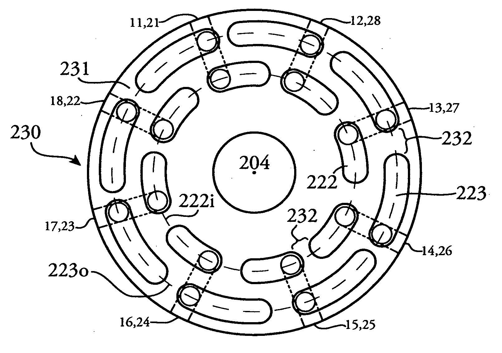
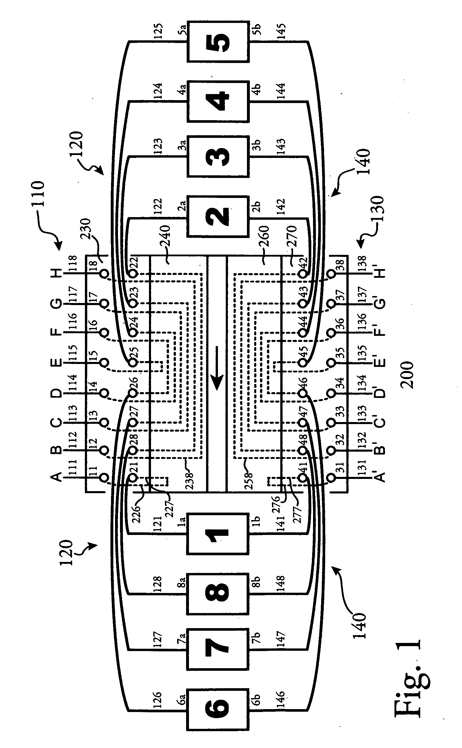
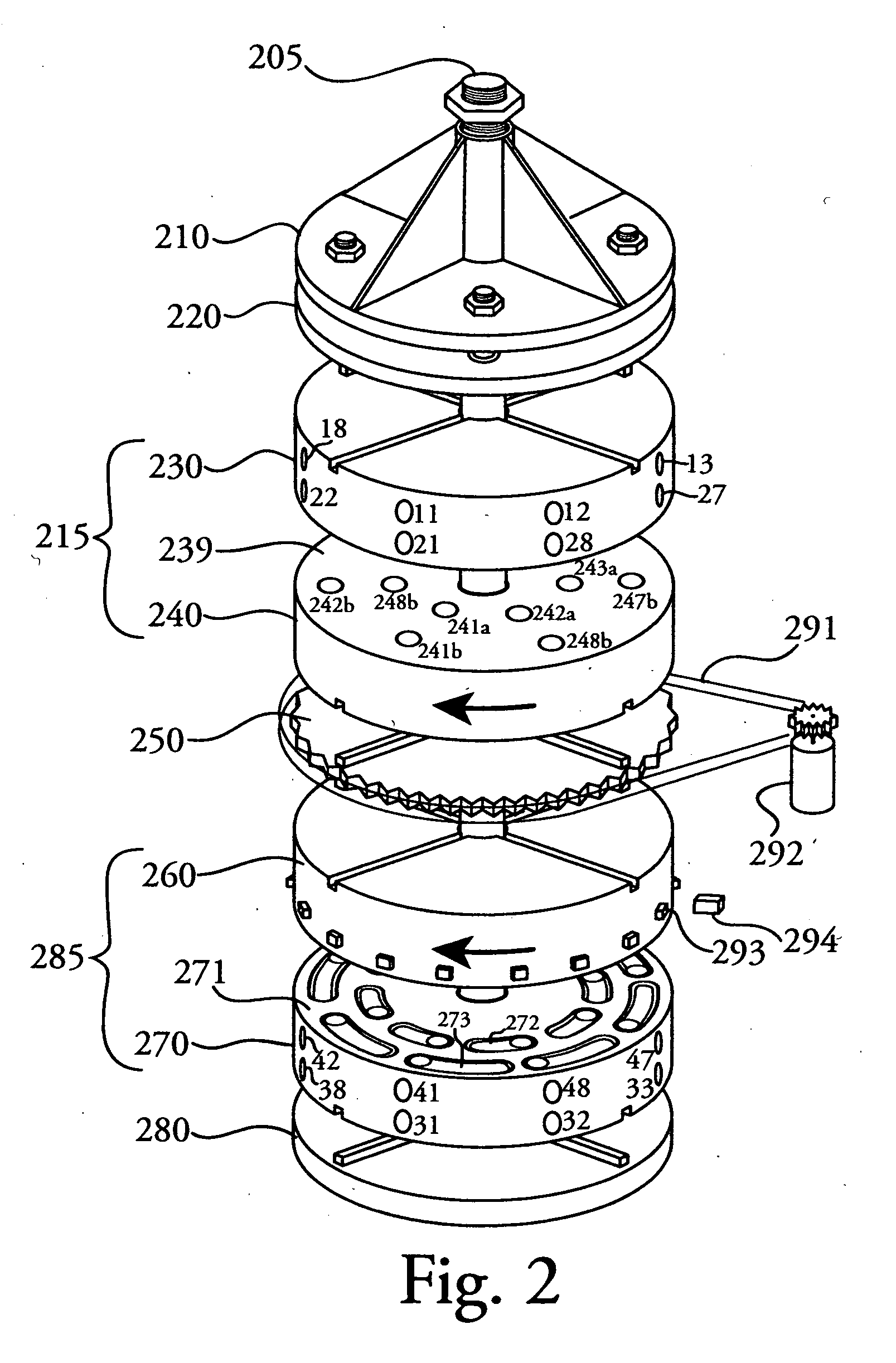
[0046]Referring to FIG. 1, invention 200 is shown in a schematic with a plurality of fluid contacting chambers 1-8. Chambers 1-8 have a first connection 1a-8a that connect by conduits 120 to multiport valve 200 at ports labeled 21-28. The same chambers 1-8 have a second connection 1b-8b that connect by conduits 140 to multiport valve 200 at ports labeled 41-48. Process streams A-H connect by conduits 110 with multiport valve 200 through ports 11-18 and are in connection with chamber connections 21-28 by internal conduits 226, 238 and 227. Process streams A′-H′ connect by conduits 130 to the same multiport valve 200 through ports 31-38 and are in connection with chamber connections 41-48 by internal conduits 276, 258 and 277. For the sake of clarity, labels 226 and 227 refer to all similar internal conduits on stationary head 230 while labels 276 and 277 refer to all similar internal conduits on stationary head 270. Labels 238 and 258 refer to all internal transverse channels in rota...


PUM

PropertyMeasurementUnit
radiusaaaaaaaaaa
diameteraaaaaaaaaa
widthaaaaaaaaaa

Abstract

A multiport rotary valve apparatus for directing fluid streams which has two circular stationary heads and two circular rotating heads. The first stationary head has at least two and preferably more primary ports for connection with fluid streams and a corresponding number of secondary ports for connection to fluid-solid contacting chambers. The second stationary head has the same number of primary ports as the first stationary head (at least two and preferably more) for connection with the fluid streams and the same number of secondary ports for a second connection to the fluid-solid contacting chambers. Each stationary head includes internal conduits for the connection of the primary and secondary ports to a rotating head. The first rotating head is in communication with the first stationary head while the second rotating head is in communication with the second stationary head. Each rotating head has internal transverse conduits formed therein for the purpose of redistributing the flow coming from a primary port in the stationary head back to the secondary port in the same stationary head. In conjunction with offset and recessed arcuate obround windows in either the stationary or rotating heads, the internal transverse conduits in the rotating heads are formed in a very specific pattern that allows each primary port to connect to each secondary port and thereby each fluid-solid contacting chamber in a sequential manner upon one index of the rotating heads. The timing of the index can be varied to accommodate the specifics of each process. The net effect of the apparatus is the simulated movement of each chamber through the various fluid streams without physically moving the chambers.

Description

[0001]This application claims benefit under Title 35 USC, §119(e) of U.S. provisional patent application Ser. No. 61 / 277,047 filed Sep. 21, 2009.FIELD OF THE INVENTION[0002]This invention relates to valves, in particular a simplified rotary valve for simultaneously directing a plurality of fluid streams sequentially into and out of a plurality of fluid-solid contacting chambers employed for purifying, treating and separating fluids.BACKGROUND OF THE INVENTION[0003]Fluid-solid contacting systems have evolved over the years from simple batch operations to more advanced systems that attempt to simulate counter-current continuous flow operations sometimes termed “simulated moving beds” (SMB) in chromatographic separations or “continuous contactors” in ion exchange or adsorption type processes. These SMB systems or continuous contactors only simulate movement of a solid counter current to a fluid since they do not truly and continuously move the solid through the fluid. In essence, any o...

Claims


Application Information

Patent Timeline
Patent Type & Authority Applications(United States)
IPC IPC(8): F16K11/074
CPCF16K11/074Y10T137/86863Y10T137/86533
Inventor PEDERSON, BRIAN KEITHAHLGREN, BRAD KEVIN
Owner GULF SEA VENTURES
Why Eureka
Try Eureka