Clamping unit

a technology of power chuck and clamping force, which is applied in the direction of turning apparatus, sleeve/socket joint, mechanical apparatus, etc., can solve the problems of high susceptibility to malfunction, high investment cost, and high requirements on operating personnel, and achieve the effect of low design complexity, reliable avoidance of accidents during operation, and no lessening of clamping force of power chuck

Inactive Publication Date: 2011-03-24
HIESTAND KARL
View PDF9 Cites 2 Cited by
  • Summary
  • Abstract
  • Description
  • Claims
  • Application Information

AI Technical Summary

Benefits of technology

[0019]If a clamping unit for machine tools is embodied in accordance with the present invention, it is possible for the rotational movements of the machine spindle to be directed through the clamping unit and for the adjustment movements of differently configured electrical clamping devices to be converted into axial adjustment movements with the help of the clamping unit and for them to be transmitted directly to a draw rod. The design complexity required to achieve this is very low, although the principal advantage is that no complicated electrical control devices and programs are required for control purposes in order to adjust and adapt the power chuck to different oper...

Problems solved by technology

Quite apart from the very great control complexity, this not only leads to a high susceptibility to malfunctions, but also the investment costs, in particular for the control device and the various programs, are considerable.
However, the principal disadvanta...

Method used


Image

  • Clamping unit
  • Clamping unit
  • Clamping unit

Examples


Embodiment Construction

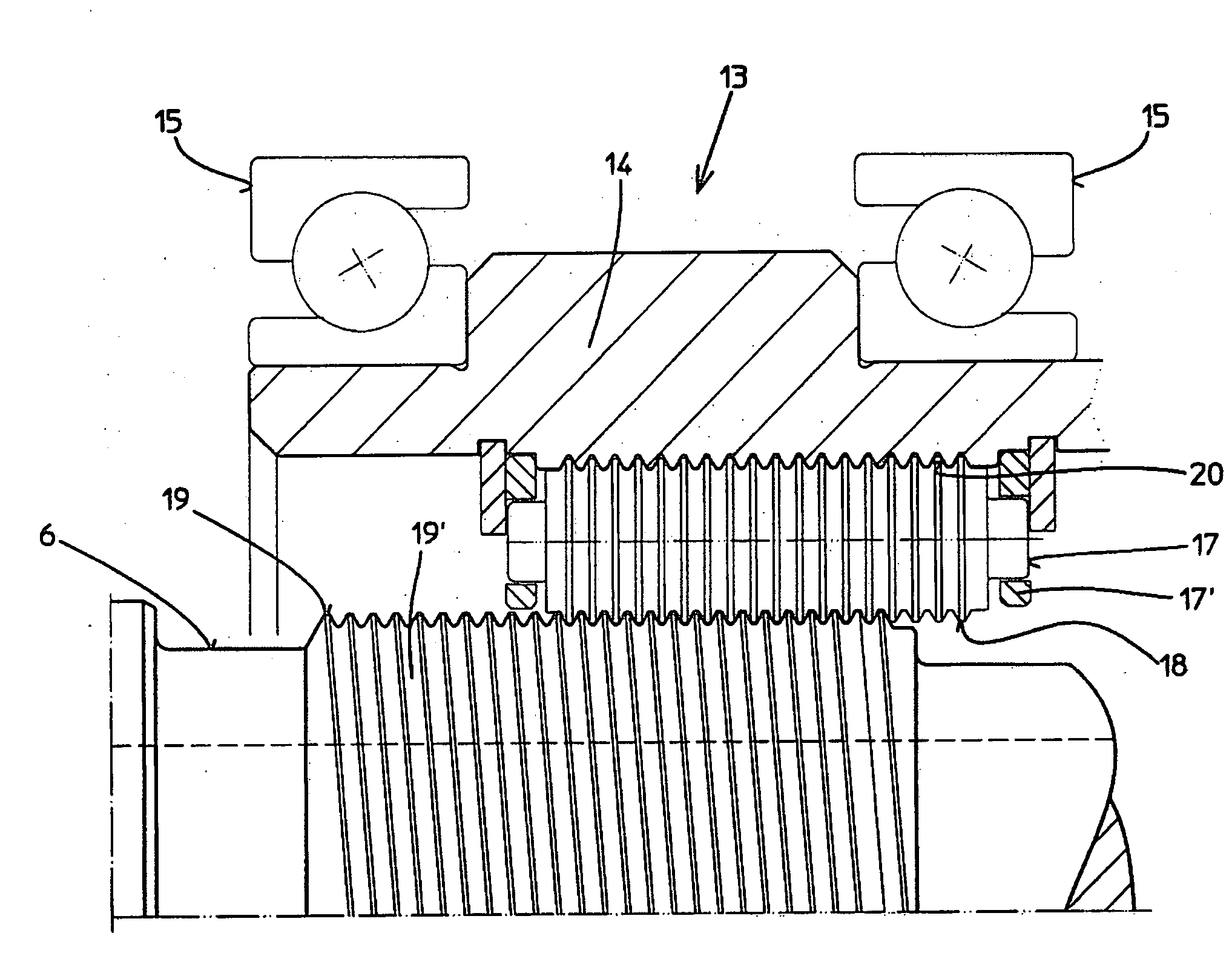
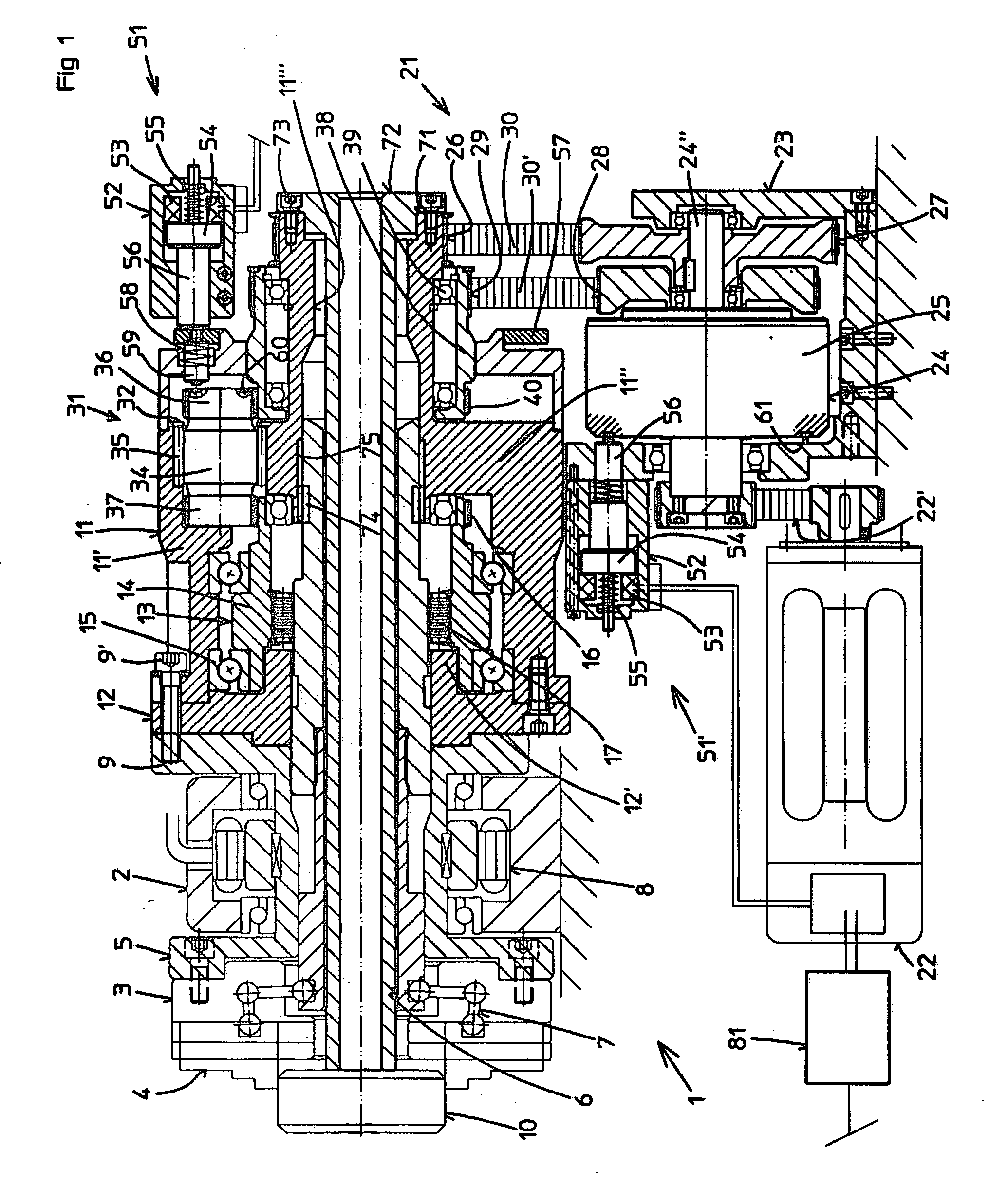
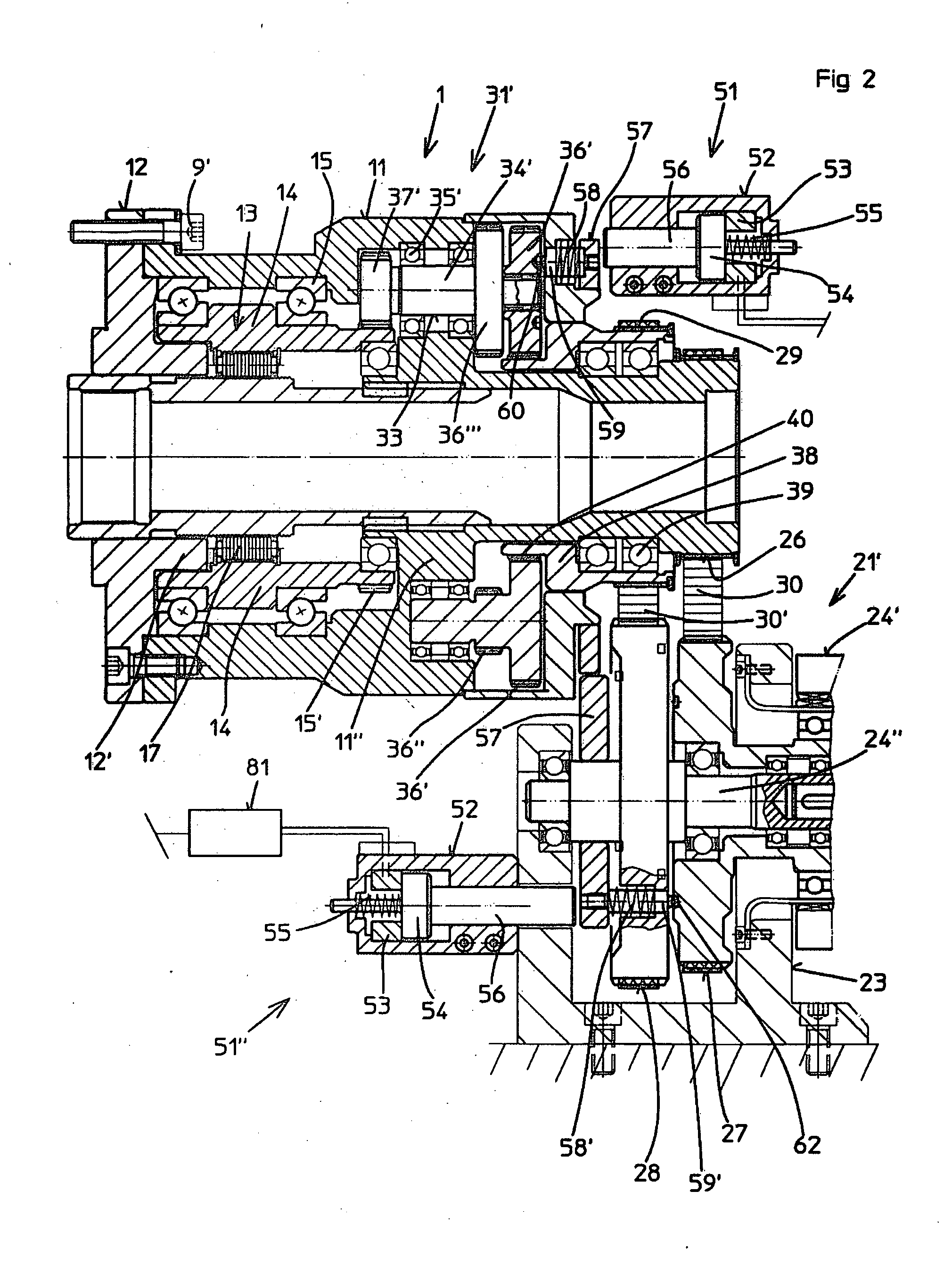
[0026]The clamping unit illustrated in FIGS. 1 and 2, in each case identified by 1, is used for transmitting a rotational movement of a machine spindle 5 of a machine tool 2 onto an actuator 21 or 21′ configured as an electrical clamping device, as well as for converting the rotational adjustment movements supplied by these actuators to the clamping unit 1, into translational movements which are to be supplied to a power chuck 3 arranged on the machine tool 2, in which case a workpiece 10 is clamped in the power chuck 3 for the purpose of machining. The power chuck 3 has radially adjustable clamping jaws 4 for this purpose, which can be adjusted via relay levers 7 by means of a draw rod 6 that can be actuated in an axial direction.

[0027]In this case, the clamping unit 1 consists of a housing 11 which is attached by bolts 9′ to a flange 9 provided on the machine spindle 5, and of a screw drive 13 that is in a driving connection with the actuator 21 or 21′ as well as the draw rod 6 by...


PUM

PropertyMeasurementUnit
Circumferenceaaaaaaaaaa

Abstract

A clamping unit (1) for machine tools (2) with a housing (11) connected in a rotationally fixed arrangement with a machine spindle, (5) and a screw drive (13) that interacts with a draw rod (6) such that rotational movements are converted into translational movements, the housing (11) being provided with an output element by which rotational movements are transmitted to an actuator (21). The housing (11) has an input element in a rotating mounting, with the actuator (21) acting on the input element, and the input element (29) is in driving connection with a shaft (14) by means of intermediate elements (31), whereby to direct rotational movements of the machine spindle (5) via the clamping unit (1), and for adjustment movements of differently configured clamping devices, to be converted into axial adjustment movements and transmitted directly onto the draw rod (6). No complicated electrical control devices and programs are required for adjusting and adapting a power chuck (3) linked to the draw rod (3) to different operating conditions.

Description

BACKGROUND OF THE INVENTION[0001]1. Field of the Invention[0002]The present invention relates to a clamping unit for machine tools with a housing that can be connected to a machine spindle in a rotationally fixed arrangement, and a screw drive arranged in the housing, wherein the screw drive interacts with a draw rod linked to a power chuck, by means of which rotational movements transmitted to the clamping unit can be converted into translational adjustment movements of the draw rod.[0003]2. Description of the Prior Art[0004]An electrical chuck with a clamping unit of this kind is disclosed in DE 10 2007 044 309 A1. In this case, the circumferential housing only serves to support the ring gear of a harmonic drive; in this configuration, there is no transmission of the rotational movement of the machine spindle onto an actuator. Instead, the actuator takes the form of an electric motor acting on a shaft generator of the harmonic drive, by means of which the rolling screw drive of th...

Claims


Application Information

Patent Timeline
IPC IPC(8): B23B31/28
CPCB23B31/16229B23B31/28B23B2260/062Y10T279/27B23B2260/128B23B2270/38B23B2260/07Y10T82/26Y10T279/20
Inventor HIESTAND, KARL
Owner HIESTAND KARL
Why Eureka
Try Eureka