Recharging system for a rechargeable battery of an inverted pendulum type vehicle

a rechargeable battery and inverter pendulum technology, which is applied in the direction of foldable cycles, cycle equipment, cycles, etc., can solve the problems of preventing the use of conventional recharging systems for inverter pendulum type vehicles, and achieve the effect of minimizing the required amount of power wiring and minimizing power loss

Active Publication Date: 2011-03-24
HONDA MOTOR CO LTD
View PDF22 Cites 41 Cited by
  • Summary
  • Abstract
  • Description
  • Claims
  • Application Information

AI Technical Summary

Benefits of technology

[0014]According to a preferred embodiment of the present invention, the vehicle comprises a frame including an upper frame and a lower frame that are separated from each other by the narrow section, and the upper frame defines a hollow interior receiving the rechargeable battery therein while the lower frame is incorporated with a drive unit that is powered by the rechargeable batter and propels the vehicle. In particular, the narrow section defines a hollow interior receiving an electric unit for controlling supply of electric power from the rechargeable batter to the drive unit. In this case, the power take device can be located adjacent to the electric unit, and this minimizes the required amount of power wiring and minimizes the power loss. Also, this arrangement contributes to the compact design of the vehicle, in particular to the minimization of the foot print of the vehicle.

Problems solved by technology

However, as an inverted pendulum type vehicle is unable to maintain an upright posture when powered off or otherwise rendered inoperative, a stand is required to maintain the vehicle in an upright posture while recharging the rechargeable battery of the vehicle, and this prevents the use of conventional recharging systems for an inverted pendulum type vehicle.

Method used


Image

  • Recharging system for a rechargeable battery of an inverted pendulum type vehicle
  • Recharging system for a rechargeable battery of an inverted pendulum type vehicle
  • Recharging system for a rechargeable battery of an inverted pendulum type vehicle

Examples


first embodiment

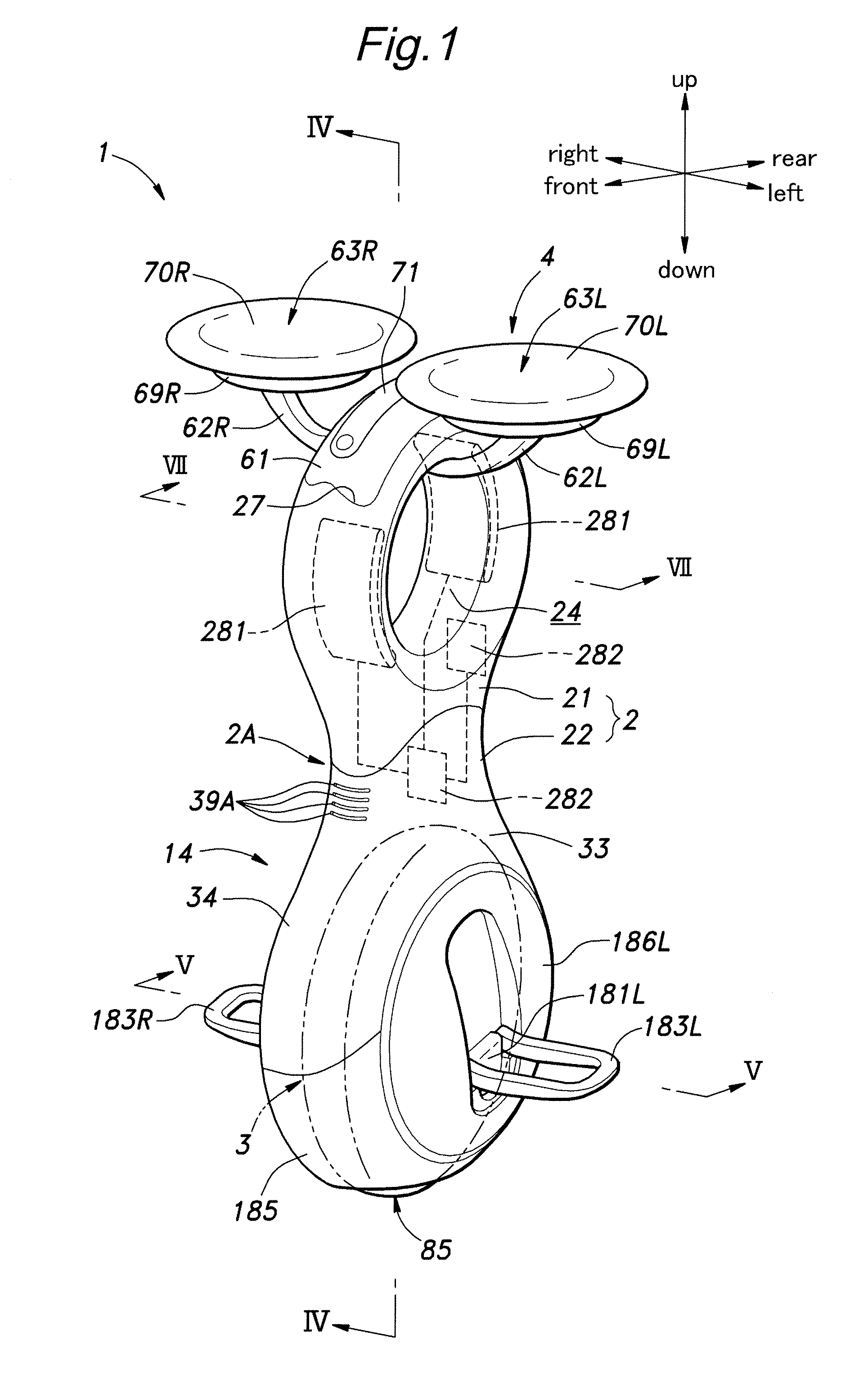
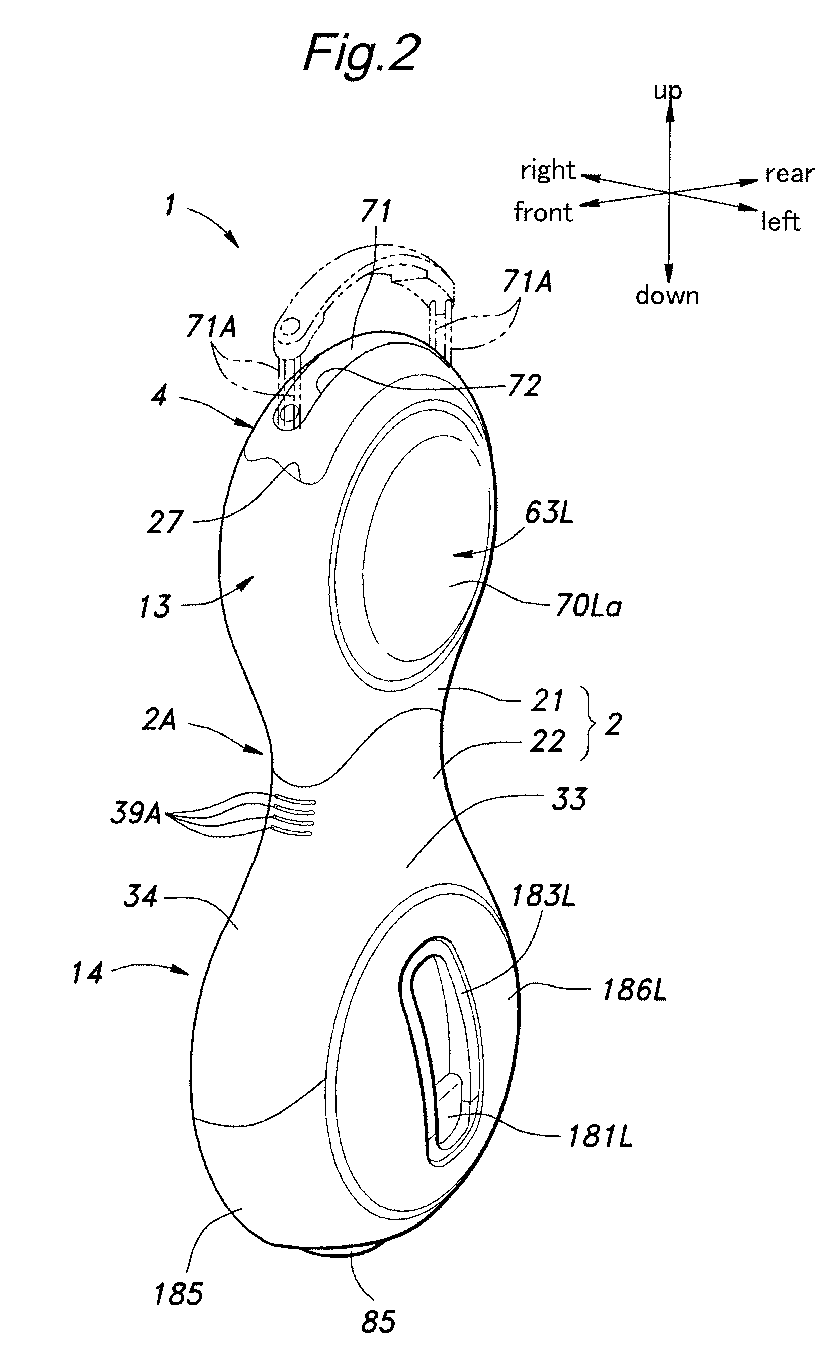
[0043]Referring to FIGS. 1, 3, 4 and 5, the inverted pendulum type vehicle 1 given as the present invention comprises a frame 2 elongated in a vertical direction, a drive unit 3 incorporated in a lower part of the frame 2, a seat assembly 4 incorporated in an upper part of the frame 2, an electric unit 11 received in an inner middle part of the frame 2 and a battery unit 10 received in an upper part of the frame 2 to power the drive unit 3 and electric unit 11 as well as various sensors. The electric unit 11 comprises an inverted pendulum control unit 5, an upper load sensor 6 and an inclination sensor 7. The control unit 5 controls the drive unit 3 according to the principle of the inverted pendulum control based on output signals received from various sensors so as to maintain the vehicle 1 in an upright posture. The sensors include a pair of step load sensors 8 and rotary encoders 9.

[0044]Referring to FIG. 1, the frame 2 is formed as a hollow shell, and have a substantially great...

second embodiment

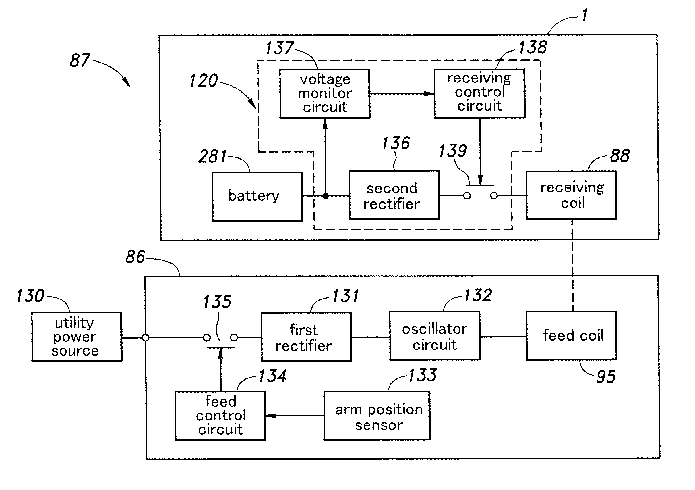
[0137]When the vehicle 1 is desired to be charged, the road contact area of the main wheel 85 is received in the recess 92, and the rear side of the upper frame 21 is leaned against the front wall 103 of the casing 93. Then, the lever arm 118 is turned in an appropriate direction to cause the two arm members 96 to move toward each other. This causes the contacts of the stand-side connector 152 to come into engagement with the corresponding contacts of the vehicle-side connector 151. Thereby, the electric contact between the vehicle-side connector 151 and stand-side connector 152 can be established. In other words, in the second embodiment, the holding of the vehicle 1 between the arm members 96 and the electric connection between the vehicle-side connector 151 and stand-side connector 152 can be simultaneously effected by the turning of the lever arm 118.

[0138]In the second embodiment, because the feed coil 95 and receiving coil 88 are replaced by the vehicle-side connector 151 and ...


PUM


Abstract

A recharging system for a rechargeable battery (281) of an inverted pendulum type vehicle (1) comprises a stand (86) for holding the vehicle in a substantially upright posture by using a supporting member (91, 96) that engages a prescribed part of the vehicle, a power feed device (95, 152) is provided on the stand, and a power take device (88, 151) provided on the vehicle. The power take device is positioned so as to couple with the power feed device when the prescribed part of the vehicle is engaged by the supporting member of the stand. The stand allows the vehicle to be placed in an upright posture simply leaning the vehicle against a part of the supporting member, and the electric connection between the rechargeable battery of the vehicle and the power source can be established at the same time without requiring any extra effort.

Description

TECHNICAL FIELD[0001]The present invention relates to a recharging system for a rechargeable battery of an inverted pendulum type vehicle.BACKGROUND OF THE INVENTION[0002]Known is an inverted pendulum type vehicle or an omni-directional vehicle comprising a pair of drive assemblies individually actuated by electric motors and a main wheel held between the drive assemblies and frictionally driven by the drive assemblies. See WO2008132779A1 (US20100096905A1) (patent document 1) for instance. Each drive assembly comprises a drive disk coaxially opposing the drive disk of the other drive assembly and a plurality of drive rollers obliquely arranged along the circumference of the drive disk at a regular interval so as to be individually rotatable. The main wheel comprises a ring-shaped annular member rotatably supported by a frame around a central axial line thereof and a plurality of driven rollers arranged along the circumference of the annular member so as to be rotatable around the re...

Claims


Application Information

Patent Timeline
Patent Type & Authority Applications(United States)
IPC IPC(8): H02J7/16H02J7/00
CPCB62J1/005B62J25/00B62K2207/02B62K3/007B62K15/00B62K1/00B62K11/007B62J45/4151
Inventor GOMI, HIROSHIHAMAYA, KAZUSHIAKIMOTO, KAZUSHIUEBAYASHI, YUICHIKOBASHI, SHINICHIROWAITA, HIRONORI
Owner HONDA MOTOR CO LTD
Why Eureka
Try Eureka