Switching converter having a plurality N of outputs providing N output signals and at least one inductor and method for controlling such a switching converter
a switching converter and output signal technology, applied in the direction of power conversion systems, dc-dc conversion, instruments, etc., can solve the problems of serious cross regulation, large ripples, and large ripples
Active Publication Date: 2011-03-24
DIALOG SEMICONDUCTOR GMBH +1
View PDF10 Cites 58 Cited by
- Summary
- Abstract
- Description
- Claims
- Application Information
AI Technical Summary
Benefits of technology
"The patent describes a switching converter that has multiple outputs and an inductor. The converter includes a first controlling device that controls the energy flow to the outputs based on a first control signal. The converter also has at least one additional fly capacitor that can be added to reduce ripples and spikes in the output signals. The first controlling device can weight the feedback signals from the outputs based on the second control signal and the output current. The addition of the fly capacitor can also help with cross regulation. The method for controlling the converter involves receiving the feedback signals, weighting them, and controlling the energy flow based on the weighted signals. The technical effects of the invention include improved stability and reduced ripples and spikes in the output signals."
Problems solved by technology
This simplifies the control loop, but has larger ripples and is only suited for small load currents.
The converter in [5] works in Continuous Conduction Mode (CCM) and adopts several Pulse Width Modulation (PWM) controllers driven by suitable linear combinations of output errors, which can sustain large load currents, but has large ripples (150 mV) and serious cross regulation (120 mV) problems.
So, the existing SIMO converters realize multiple-output with some parasitic effects:Load currents are limited by the intrinsic requirement of Discontinuous Conduction Mode (DCM) and pseudo-CCM (PCCM) control.Large ripples and spikes, resulting from discontinuous current change on filter capacitors with parasitic series inductors.Cross regulation: the SIMO converter can be regarded as a multi-input multi-output system with cross regulation items.Efficiency: more switches added in the power path result in more power loss.
The efficiency gets worse especially under light loads.
However, as pointed out in [1], there may occur serious cross regulation problems.
This is the cross regulation problem, which is one of the severest challenges in SIMO converter design.
However, this method is not suitable for the SIDO converter in CCM.
Another serious problem is large spikes, which are caused by the rapid current change on the equivalent series inductors (ESLs) of filter capacitors when switching S3 and S4.
Method used
View moreImage
Smart ImageViewing Examples


Examples
first embodiment
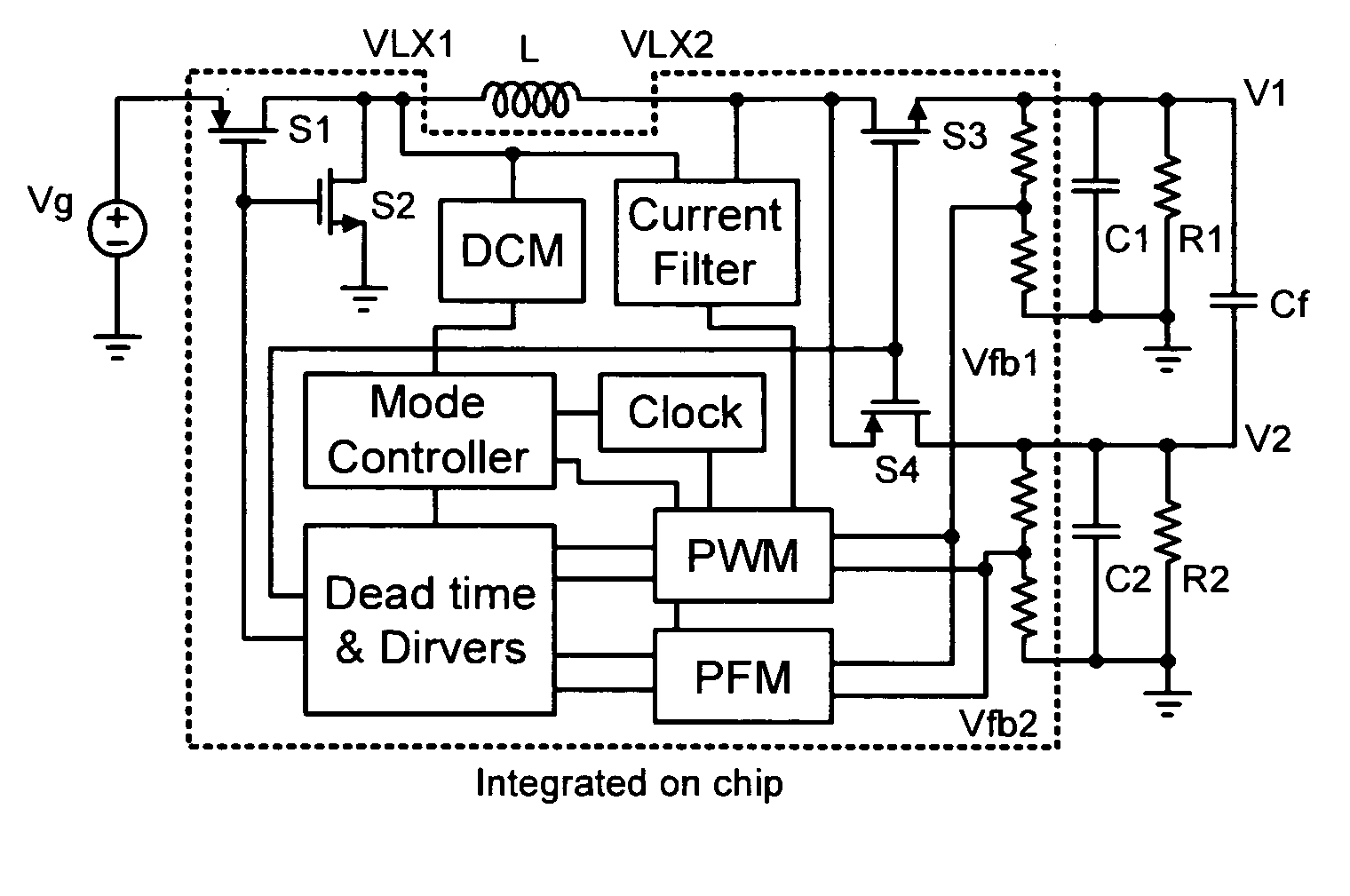
[0061]FIG. 9 shows a switching converter;
second embodiment
[0062]FIG. 10 shows a switching converter;
[0063]FIG. 11 shows PWM mode measured waveforms of output ripples and nodes VLX1 and VLX2 at heavy loads I1=400 mA, I2=200 mA, FIG. 11(a) without Cf, FIG. 11(b) with Cf;
[0064]FIG. 12 shows PFM mode measured waveforms of output ripples and nodes VLX1 and VLX2 at light loads I1=33 mA, I2=10 mA, FIG. 12(a) without Cf, FIG. 12(b) with Cf;
[0065]FIG. 13 shows an embodiment of a method for controlling a switching converter; and Like or functionally alike elements in the figures have been allocated the same reference signs if not otherwise indicated.
Login to View More PUM
 Abstract
This invention provides a switching converter having a plurality N of outputs providing N output signals and at least one inductor, comprising a first controlling device for controlling the total energy flowing over the inductor to the N outputs dependent on a first control signal, at least a second controlling device for distributing the total energy between the N outputs by means of at least a second control signal, wherein the first controlling device is coupled to all N outputs for receiving a number M of the respective feedback output signals of the N outputs, M≦N, wherein the first controlling device comprises first means for weighting the M feedback output signals and second means for providing the first control signal dependent on the weighted M feedback output signals.
Description
[0001]This application claims benefit under 35 U.S.C. §119 to U.S. Provisional Patent Application Ser. No. 61 / 242,182, filed on Sep. 14, 2009, which is herein incorporated by reference in its entiretyTECHNICAL FIELD[0002]The present invention relates to a switching converter having a plurality N of outputs providing N output signals and at least one inductor and to a method for controlling such a switching converter. In particular, the present invention relates to a single-inductor dual-output switching converter with low ripples and improved cross regulation.BACKGROUND[0003]Portable applications usually need different supply voltages for different functional modules to minimize power consumption. A more interesting and efficient solution is to use one converter with a single inductor to generate multiple outputs, which reduces the external components and saves cost.[0004]There have been several kinds of single-inductor multiple-output (SIMO) switching converters reported in recent ...
Claims
Login to View More Application Information
Patent Timeline
 Patent Type & Authority Applications(United States)
IPC IPC(8): G05F1/10
CPCH02M2001/009H02M3/158H02M1/009
Inventor XU, WEIWEIHONG, ZHILIANGKILLAT, DIRK
Owner DIALOG SEMICONDUCTOR GMBH