Ground fault detection device

a detection device and ground fault technology, applied in emergency protective arrangements, testing circuits, instruments, etc., can solve problems such as lethal shocks or electrocution, ground faults are undesirable, and electrical current in circuits leakage, and achieve the effect of less noise sensitivity

Active Publication Date: 2011-03-24
ABB (SCHWEIZ) AG
View PDF12 Cites 23 Cited by
  • Summary
  • Abstract
  • Description
  • Claims
  • Application Information

AI Technical Summary

Benefits of technology

[0019]An advantage over the conventional methods afforded by various embodiments of the present invention is that the detection of a ground fault current that requires interruption of current flow for personnel protection can, more simply and with less sensitivity to noise, be discerned from a ground fault current that does not require an interruption of current flow for personnel protection.

Problems solved by technology

A ground fault is an undesirable condition in an electrical system, in which electrical current flows to the ground.
A ground fault happens when the electrical current in a circuit leaks outside of its intended flow path.
In some instances, the ground fault may result in lethal shocks or electrocution, such as in the case of a person who makes inadvertent contact with the phase conductor.
In contrast, the resistive component 31 does cause heating and does present a shock hazard.
One problem that occurs with conventional GFCI devices in circuits with a high capacitance-to-ground is unnecessary or nuisance tripping caused by the capacitive current to ground in the absence of a real, or resistive, ground fault condition.
That is, the capacitive, or reactive, currents can exceed the predetermined ground fault current threshold of conventional GFCI devices and result in a nuisance tripping of the GFCI in the protected circuits.
One known shortcoming of such a conventional method, in the instance that the ground current is noisy or non-sinusoidal, the ground fault zero crossings may alter timing measurement of the conventional method, thus resulting in an incorrect zero crossing measurement.
Moreover, since the controller must generate a pulse and measure pulses in order to determine the zero crossings and measure the time between zero crossings, the prior art methods can be complicated and subject to signaling errors.

Method used


Image

  • Ground fault detection device
  • Ground fault detection device
  • Ground fault detection device

Examples


Embodiment Construction

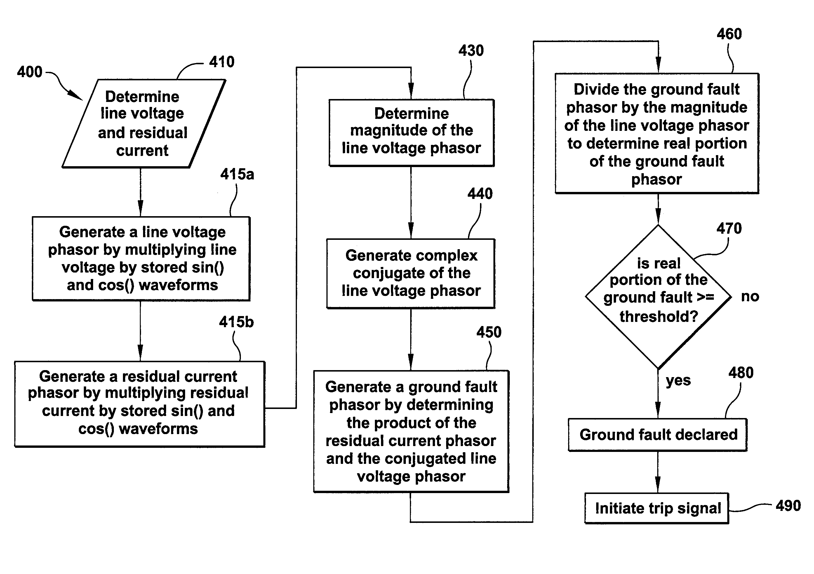
[0030]The following description makes reference to the accompanying drawings that form a part hereof, and in which is shown by way of illustration specific embodiments that may be practiced. It is understood that other embodiments may be utilized and that various changes can be made to the embodiments shown and described herein without departing from the patentable scope of the claims appended hereto. The following description is, therefore, not to be taken in a limiting sense.

[0031]As used herein, an element or function recited in the singular and proceeded with the word “a” or “an” should be understood as not excluding plural said elements or functions, unless such exclusion is explicitly recited. Furthermore, references to “one embodiment” of the claimed invention should not be interpreted as excluding the existence of additional embodiments that also incorporate the recited features.

[0032]The detailed description is divided into two sections. The first section describes method e...


PUM


Abstract

A device and method to determine the presence of a ground fault that distinguishes between the capacitive portion of the currents to ground, and the resistive portion of the currents to ground by ascertaining aspects of the voltage and residual current waveforms.

Description

BACKGROUND OF THE INVENTION[0001]1. Field of the Invention[0002]The field of the invention relates to electrical ground fault protection generally, and more particularly to certain new and useful advances in devices and methods for ground fault detection and interruption of which the following is a specification, reference being had to the drawings accompanying and forming a part of the same.[0003]2. Description of Related Art[0004]A ground fault is an undesirable condition in an electrical system, in which electrical current flows to the ground. A ground fault happens when the electrical current in a circuit leaks outside of its intended flow path. Ground fault circuit interrupters (GFCIs) or residual current devices (RCDs) are designed to protect such electrical hazards by interrupting a circuit when there is a ground fault, or residual current, such as a leakage of electrical current from an energized line conductor to ground. Conventional electric circuits normally carry balance...

Claims


Application Information

Patent Timeline
Patent Type & Authority Applications(United States)
IPC IPC(8): G01R31/14
CPCH02H3/337G01R31/025G01R31/52H02H3/16H02H3/331
Inventor ROSCOE, GEORGE WILLIAMPAPALLO, JR., THOMAS FREDERICKRIVERS, JR., CECIL
Owner ABB (SCHWEIZ) AG
Why Eureka
Try Eureka