
Display panel and sealing structure

Active Publication Date: 2011-03-24
AU OPTRONICS CORP
View PDF2 Cites 18 Cited by
  • Summary
  • Abstract
  • Description
  • Claims
  • Application Information

AI Technical Summary

Benefits of technology

[0008]Accordingly, the present invention is directed to an LCD panel with a reduced width of the frame thereof and a sealing structure having high mechanical strength.
[0009]The present invention is also directed to a sealing structure able to keep a quite high mechanical strength in a limited layout space and increase the process margin of the sealant.
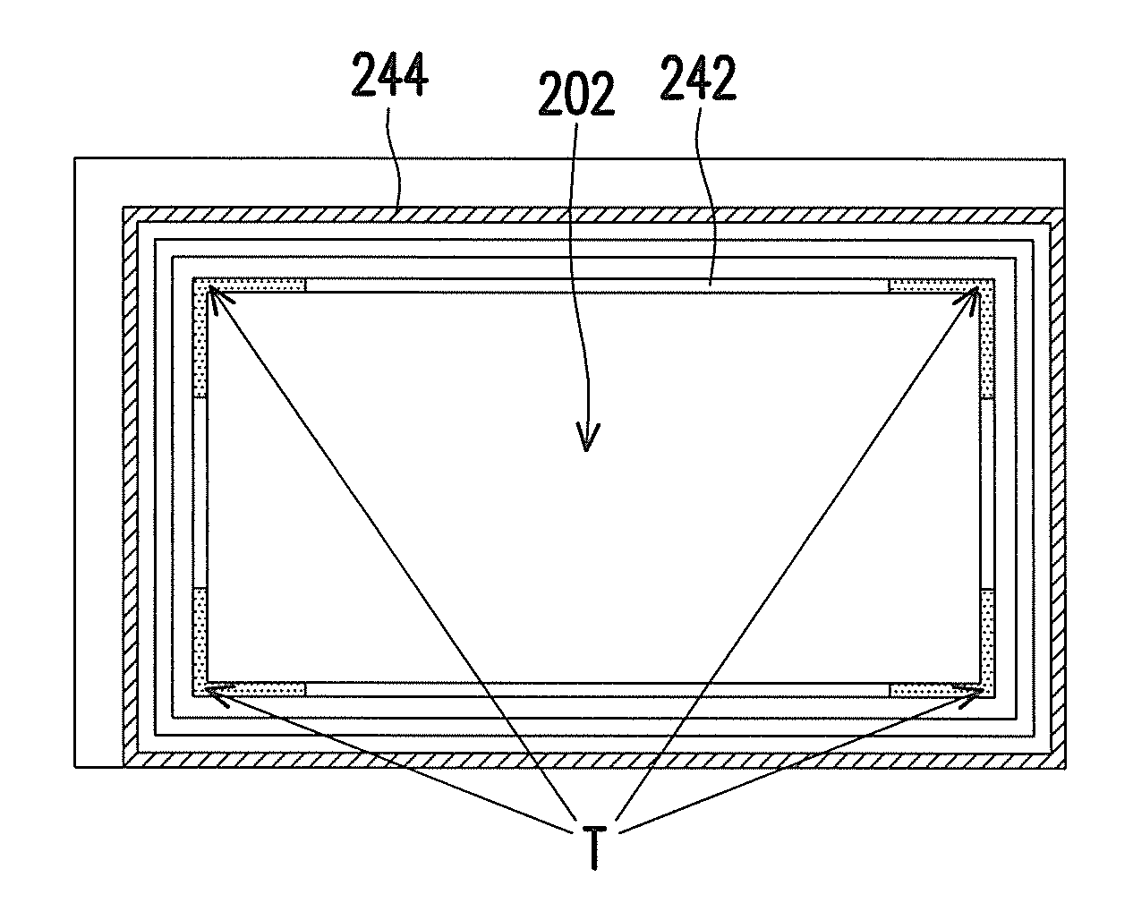
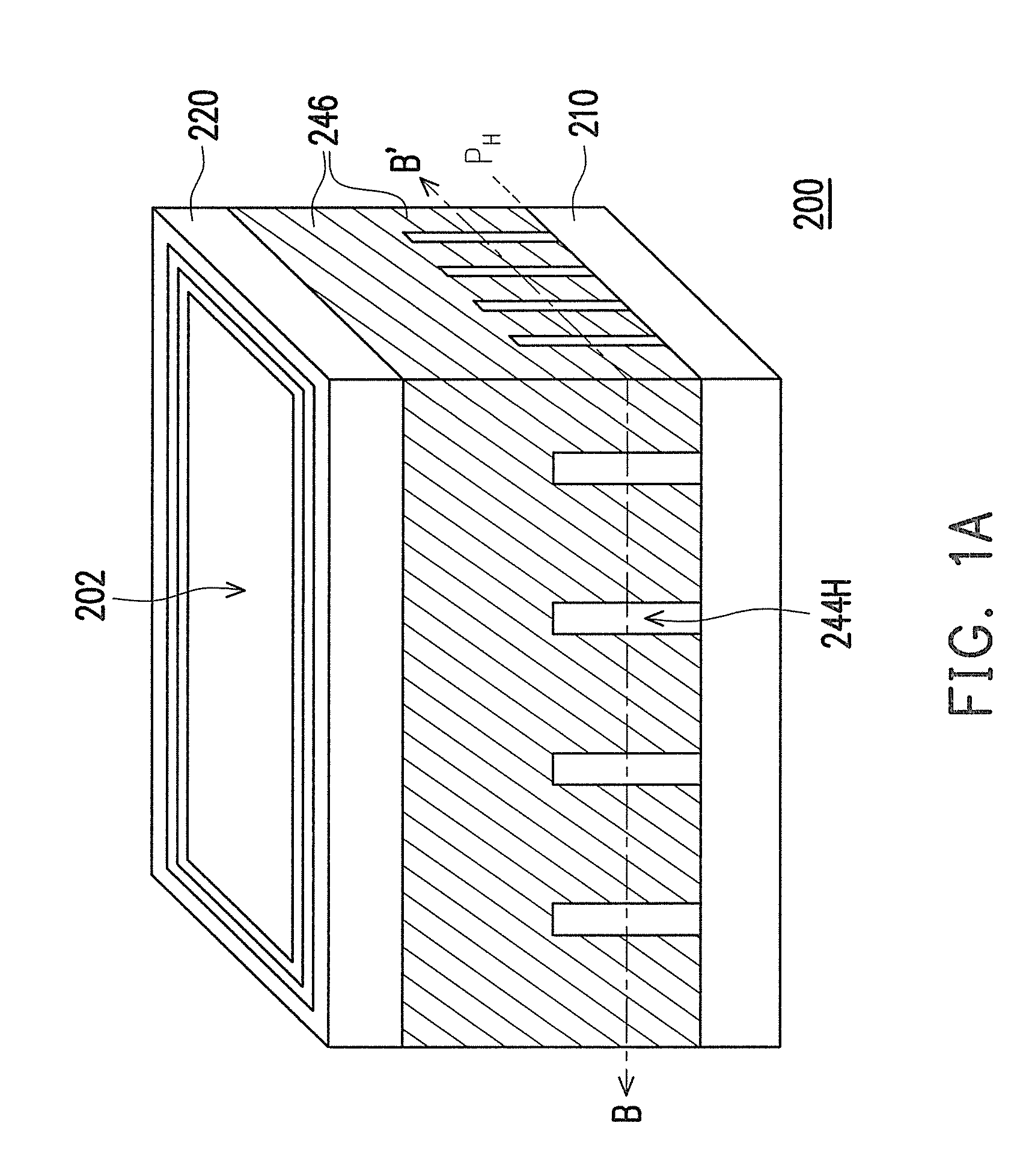
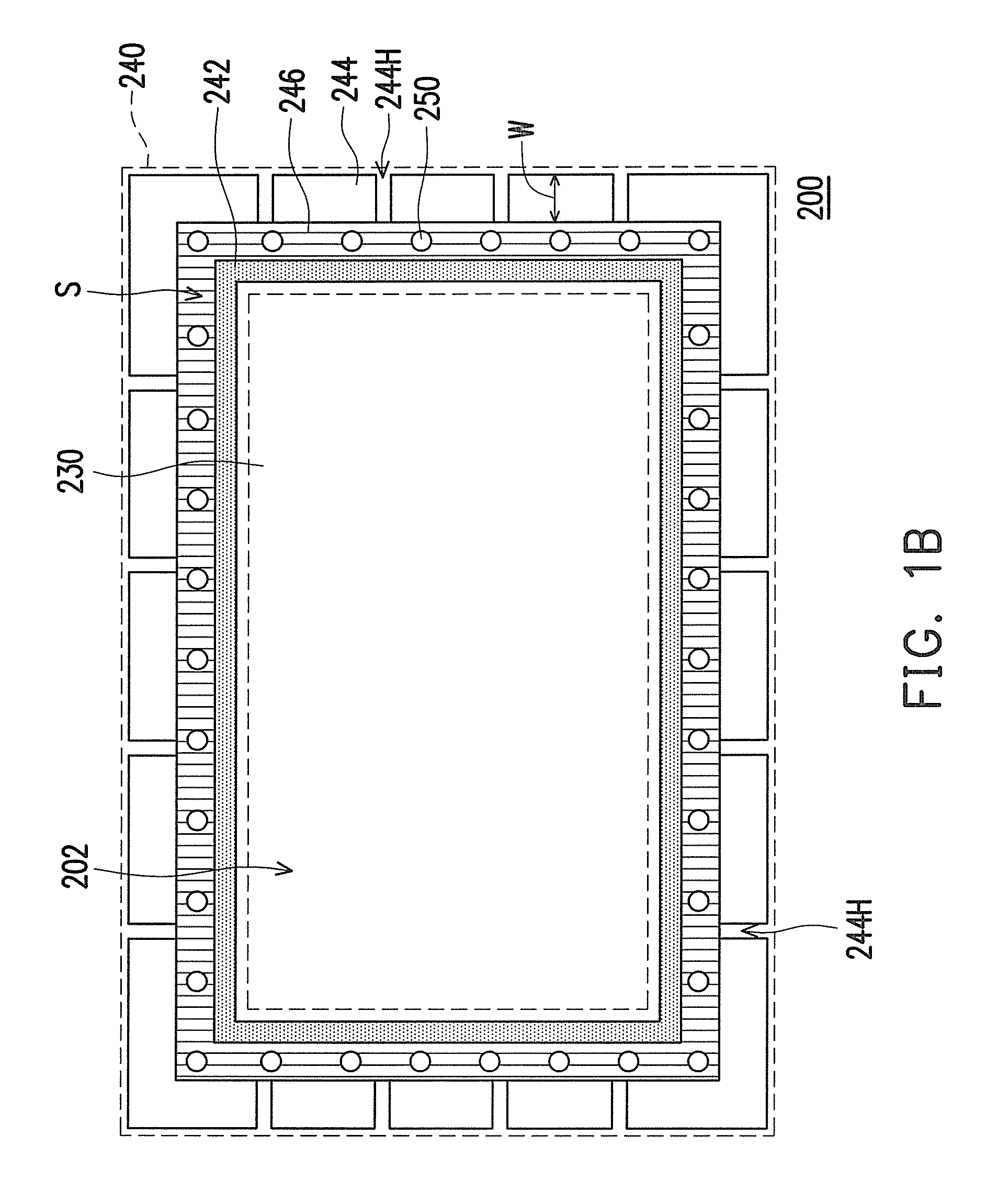
[0018]Based on the description above, the present invention employs a sealing structure with an inner wall and an outer wall wherein the outer wall contains a plurality of side wall holes. The sealant-disposing space of the sealing structure is filled with the sealant, and the partial sealant can further be distributed in the side wall holes on the outer wall, so that the adhesiveness between the sealant and the first substrate and second substrate is increased, and the downsized width of the sealant is assured not to weaken the structure strength. In addition, the sealing structure of the present invention can also enhance the process capacity and stability of the sealant process.

Problems solved by technology

However, a downsized sealant width may encounter the problems of insufficient structure strength and inadequate adhesive intensity, which results in poor reliability of the LCD panel.
Moreover in a worse situation, the TFT array substrate and the color filter substrate are easily separated from each other due to the insufficient mechanical strength or inadequate adhesive intensity of the sealant.
On the other hand, with a reduced width of the sealant, it becomes a significant issue to precisely define injecting the sealant in a limited design width, which has a great impact on the capacity and the stability of the process machine on the production line and the sealant-injecting process.

Method used


Image

  • Display panel and sealing structure
  • Display panel and sealing structure
  • Display panel and sealing structure

Examples


Embodiment Construction

[0027]The present invention mainly provides a sealing structure to seal a sealant between an inner wall and an outer wall, wherein the inner wall and the outer wall are respectively located at both sides of the sealant used to enhance the integral structure strength, so that the LCD panel with a reduced edge width of the frame thereof still performs a certain required structure strength within a limited width. In addition, during conducting a sealant process, the predetermined structure on the outer wall provides a buffered disposing space to the sealant, so that the conducted sealant process wins a larger process margin. By using the partial sealant located in the predetermined structure of the outer wall, the integral structure strength of the sealing structure and the adhesive intensity between the sealing structure and the upper and lower substrates are further enhanced. Reference will now be made in detail to the sealing structure and the LCD panel employing the sealing structu...


PUM


Abstract

An LCD panel includes a first substrate, a second substrate, a displaying medium and a sealing structure, wherein the second substrate is located at the side opposite to the first substrate and the displaying medium is located between the first substrate and the second substrate for displaying an image. The sealing structure is located between the first substrate and the second substrate to seal the displaying medium, wherein the sealing structure includes an inner wall, an outer wall and a sealant. The inner wall disposed surrounding the displaying medium and the outer wall disposed surrounding the inner wall together form a sealant-disposing space therebetween. The outer wall has a plurality of side wall holes and the sealant is disposed in the sealant-disposing space. In this way, the sealing structure is able to enhance the structure strength in a limited layout space and promote the process margin.

Description

CROSS-REFERENCE TO RELATED APPLICATION[0001]This application claims the priority benefit of Taiwan application serial no. 98132116, filed Sep. 23, 2009. The entirety of the above-mentioned patent application is hereby incorporated by reference herein and made a part of specification.BACKGROUND OF THE INVENTION[0002]1. Field of the Invention[0003]The present invention generally relates to a liquid crystal display panel (LCD panel) and a sealing structure, and more particularly, to an LCD panel and a sealing structure with a plurality of side wall holes.[0004]2. Description of Related Art[0005]The rapid development in the multimedia society today is largely attributed to the astonished progress in semiconductor devices and display apparatuses. Among various display panels, due to advantages of high display quality, high space utilization, low power consumption and no radiation with an LCD panel, the LCD panel has played a major role in the mainstream display market.[0006]Usually, an L...

Claims


Application Information

Patent Timeline
IPC IPC(8): G02F1/1339
CPCG02F1/1339
Inventor CHU, CHIH-WEIHSIEH, MING-CHEWANG, SHIH-YU
Owner AU OPTRONICS CORP
Learn More