
DC conversion apparatus

a technology of dc conversion and conversion apparatus, which is applied in the direction of dc-dc conversion, power conversion system, energy industry, etc., can solve the problems of deteriorating apparatus efficiency, transformers and switching elements generating heat and breaking, and difficulty in equalizing currents borne by current resonant converters, etc., to achieve low cost and simple configuration

Inactive Publication Date: 2011-03-24
SANKEN ELECTRIC CO LTD
View PDF8 Cites 38 Cited by
  • Summary
  • Abstract
  • Description
  • Claims
  • Application Information

AI Technical Summary

Benefits of technology

[0026]To solve the problems of the related arts mentioned above, the present invention provides a DC conversion apparatus that is manufacturable at low cost, has a simple configuration, and is capable of properly balancing currents passing through a plurality of current resonant converters that are operated at a predetermined phase difference.

Problems solved by technology

It is very difficult, therefore, to equalize currents borne by the current resonant converters.
If the currents are imbalanced, i.e., if the current resonant converters provide different current values, the efficiency of the apparatus will deteriorate and the transformers and switching elements will generate heat and break.
This involves a large cost.
Namely, this related art has a problem of increasing cost and circuit size as the number of units to be operated in parallel increases.

Method used


Image

  • DC conversion apparatus
  • DC conversion apparatus
  • DC conversion apparatus

Examples


embodiment 1

Modification of Embodiment 1

[0069]FIG. 6 is a circuit diagram illustrating a DC conversion apparatus according to a modification of Embodiment 1. The modification of FIG. 6 differs from Embodiment 1 of FIG. 3 in that the modification additionally has a voltage dividing circuit including voltage dividing capacitors C10 and C20.

[0070]The voltage dividing circuit has the same number of capacitors as the number of current resonant converters employed by the DC conversion apparatus. The two voltage dividing capacitors C10 and C20 are employed to the modification.

[0071]These capacitors are connected in series, to divide a source voltage from a DC power source Vin and supply DC power to each of the current resonant converters.

[0072]The voltage dividing capacitor C10 is connected in parallel with a series circuit of switching elements Q11 and Q12. The voltage dividing capacitor C20 is connected in parallel with a series circuit of switching elements Q21 and Q22.

[0073]The DC conversion appar...


PUM


Abstract

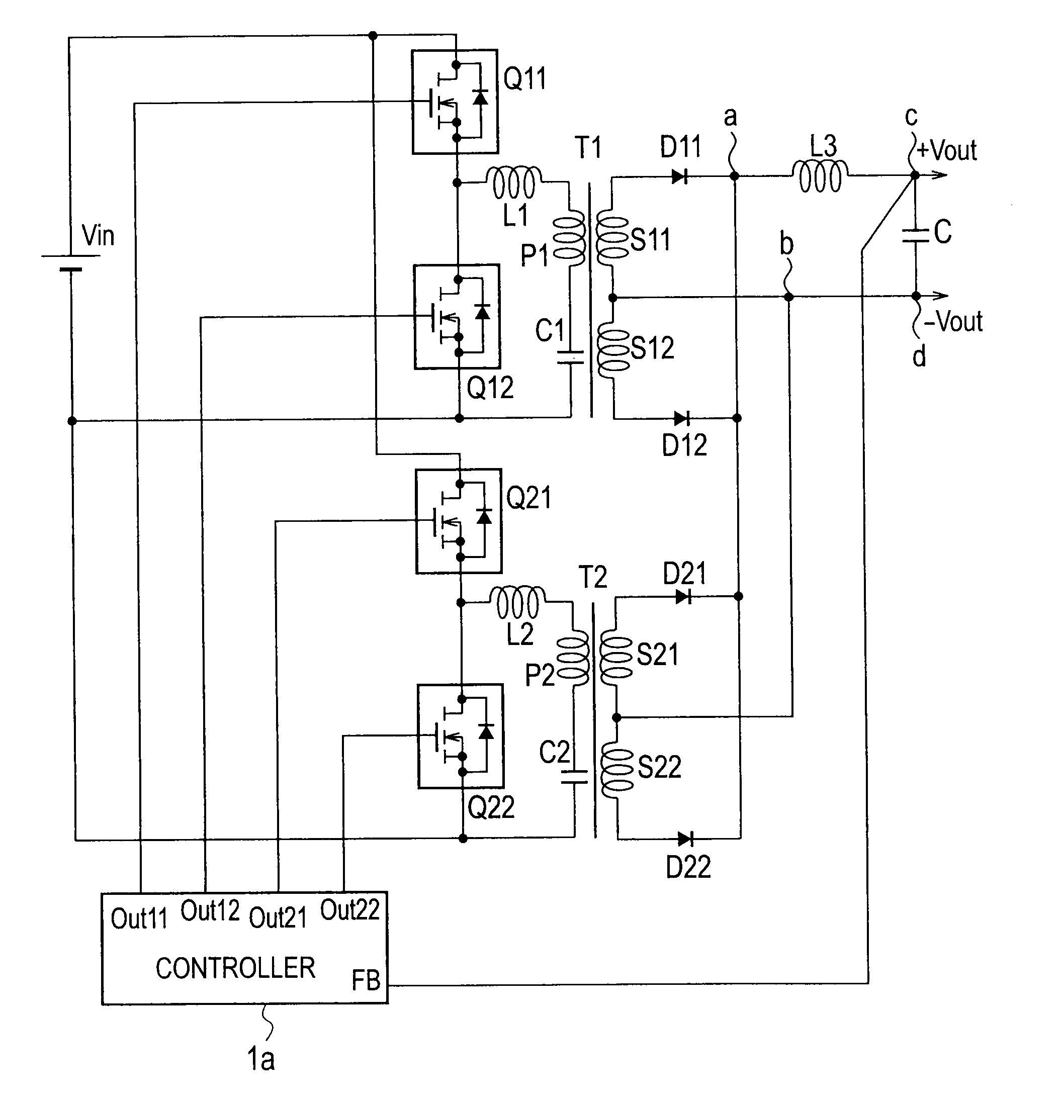
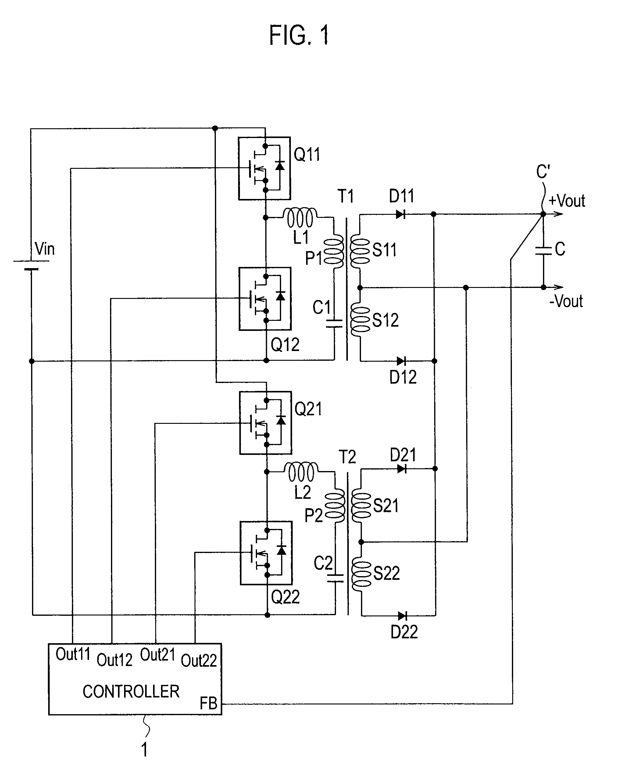
A DC conversion apparatus includes a plurality of current resonant converters. Each of the current resonant converters has two switching elements connected in series, a transformer having primary and secondary windings, a series resonant circuit including a resonant reactor, the primary winding of the transformer, and a resonant capacitor, and a rectifying circuit to rectify a voltage generated by the secondary winding of the transformer. The DC conversion apparatus also includes a smoothing circuit having a reactor L3 and a smoothing capacitor C and arranged after connection points to which output terminals of the rectifying circuits of the plurality of current resonant converters are commonly connected. The DC conversion apparatus further includes a controller to control, according to an output voltage from the smoothing circuit, ON / OFF of the two switching elements of each of the plurality of current resonant converters.

Description

BACKGROUND OF THE INVENTION[0001]1. Field of the Invention[0002]The present invention relates to a DC conversion apparatus having a plurality of current resonant converters that are controlled to have a phase difference.[0003]2. Description of the Related Art[0004]DC conversion apparatuses with current resonant converters have been used as high-efficiency, low-noise power source apparatuses. Generally, the DC conversion apparatus switches power from a DC power source into a switching output through a switching circuit, supplies the switching output to a resonant circuit, provides a resonant output from windings of a transformer in the resonant circuit, and converts the resonant output into a DC output. When large output power is needed, the DC conversion apparatus must be designed in consideration of an increase in the temperature of the transformer and other parts. This results in enlarging the size of the apparatus and increasing the cost thereof.[0005]To provide large output powe...

Claims


Application Information

Patent Timeline
Patent Type & Authority Applications(United States)
IPC IPC(8): H02M3/335
CPCY02B70/1433H02M3/33569Y02B70/10Y02P80/10H02M3/33571H02M3/01
Inventor CHIBA, AKITERU
Owner SANKEN ELECTRIC CO LTD
Learn More