Antenna array, network planning system, communication network and method for relaying radio signals with independently configurable beam pattern shapes using a local knowledge

a technology of local knowledge and antenna array, applied in the field of antenna array with independently configurable beam pattern shape, can solve the problems of increasing the number of base stations, increasing the interference level between the cells of the mobile communication network, and increasing the interference caused by users outside the cell

Active Publication Date: 2011-03-24
TELEFON AB LM ERICSSON (PUBL)
View PDF51 Cites 70 Cited by
  • Summary
  • Abstract
  • Description
  • Claims
  • Application Information

AI Technical Summary

Benefits of technology

[0028]The term communication network as used herein shall be construed as a mobile communication network ...

Problems solved by technology

It is expensive for the operators to increase the number of the base stations.
With the increased number of the base stations a level of inter...

Method used


Image

  • Antenna array, network planning system, communication network and method for relaying radio signals with independently configurable beam pattern shapes using a local knowledge
  • Antenna array, network planning system, communication network and method for relaying radio signals with independently configurable beam pattern shapes using a local knowledge
  • Antenna array, network planning system, communication network and method for relaying radio signals with independently configurable beam pattern shapes using a local knowledge

Examples


Embodiment Construction

[0041]For a better understanding of the present disclosure reference shall now be made to preferred aspects of the present disclosure, examples of which are illustrated in the accompanying drawings.

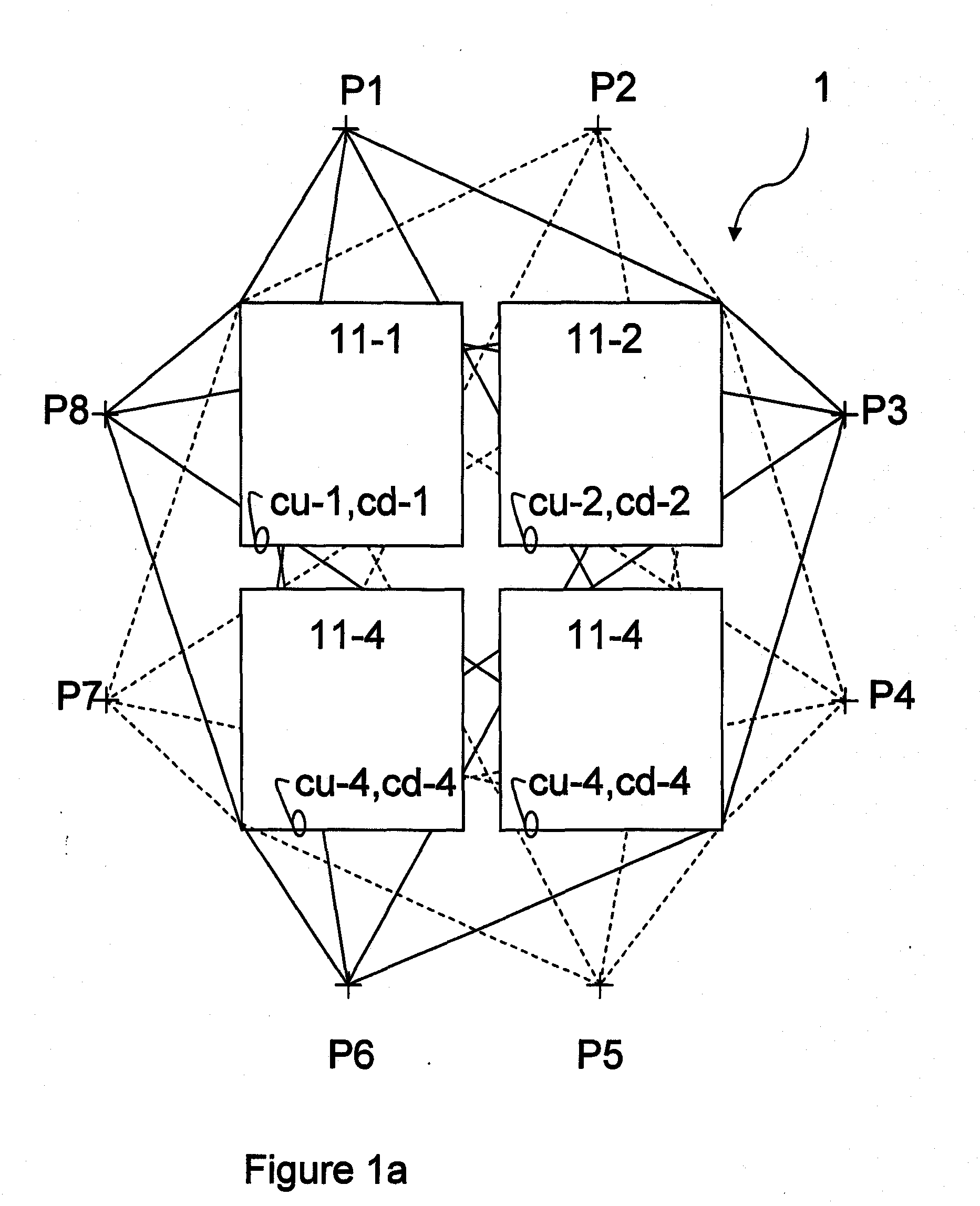
[0042]FIG. 1a shows an antenna array 1 of the present disclosure. The antenna array 1 comprises four antenna elements 11-1, 11-2, 11-3, 11-4. Without any limitation the antenna array 1 may comprise more than four of the antenna elements 11-1, 11-2, . . . , 11-j. Antenna arrays known in the prior art allow a beam steering. The beam steering is provided by providing a defined phase and amplitude relation between the antenna elements 11-1, 11-2, . . . , 11-j. In the prior art the phase and amplitude relation is fixed between individual ones of the antenna elements 11-1, 11-2, . . . , 11-j. Typically passive combiner networks are used in order to combine a received signal. Likewise fixed amplitudes and phases are used in order to provide the defined phase and amplitude differences between the...


PUM


Abstract

The present disclosure provides an antenna array (1) for relaying radio signals into a cell (10) of a communication network (500). The antenna array (1) comprises a plurality of uplink beam forming vectors (20u) selectable as an uplink beam shape for an uplink relaying and a plurality of downlink beam forming vectors (20d) selectable as a down link beam shape for a down link relaying. The plurality of uplink beam forming vectors (20u) and/or the plurality of the downlink beam forming vectors (20d) may be adjusted at a digital radio interface and forwarded from the digital radio interface to the antenna array (1). An individual one (22u) of the plurality of uplink beam forming vectors (20u) and an individual one (22d) of the plurality of downlink beam forming vectors (20d) are independently selectable using a local knowledge (60) about the cell 10. The present disclosure further provides a communication network (500) comprising a plurality of the antenna arrays (1-1, 1-2, . . . , 1-N) for relaying radio signals into the communication network (500). The communication network (500) further comprises a network playing system (200) adapted to independently select an individual one (22u-1, 22u-2, . . . , 22u-N) of the plurality of uplink beam forming vectors (20u-1, 20u-2, . . . , 20u-N) and an individual one (22d-1, 22d-2, . . . , 22d-N) of the plurality of downlink beam forming vectors (20d-1, 20d-2, . . . , 20d-N) for at least one of the antenna arrays (1-1, 1-2, . . . , 1-N) using a local knowledge (600) about the communication network (500). The present disclosure further provides a method for relaying radio signals into a cell (10) of the communication network (500), a method (2000) for planning the communication network (500), and a method (5000) for relaying radio signals into cells (10-1, 10-2, . . . , 10-N) of the communication network (500); all methods (1000, 2000, 5000) using a local knowledge (600) about the network (500) and or a local knowledge (60-1, 60-2, . . . , 60-N) about the cells (10-1, 10-2, 10-3 . . . , 10-N).

Description

CROSS REFERENCE TO OTHER APPLICATIONS[0001]The present application is related to a Patent Application entitled “User Group specific Beam Forming in a Mobile Network” (Attorney Docket No. 4424-P04916US0) filed concurrently herewith. The entire disclosure of the foregoing application is incorporated herein by reference.FIELD OF THE INVENTION[0002]The field of the invention relates to an antenna array with independently configurable beam pattern shapes.BACKGROUND OF THE INVENTION[0003]With the increasing use of mobile communications systems, operators of mobile communications systems need more transmitters, receivers and / or transceivers relaying into cells of the mobile communications systems, such as for example base stations, in order to meet the increased demand for telecommunications.[0004]It is expensive for the operators to increase the number of the base stations. Maintenance of the base stations may, for example, require an engineer to be present at the site of the base station...

Claims


Application Information

Patent Timeline
IPC IPC(8): H04L12/28H01Q21/00
CPCH01Q1/246H04B7/0408H04W16/28H04L2025/03426H04L2025/03808H04L25/03343
Inventor SCHMIDT, GEORGWECKERLE, MARTINSCHLEE, JOHANNESNEUMANN, DIRKFUCHS, JOHANNES
Owner TELEFON AB LM ERICSSON (PUBL)
Why Eureka
Try Eureka