
Apparatus and operating method of digital RF receiver in a wireless communication system

a digital radio frequency and receiver technology, applied in the direction of digital transmission, multiple modulation transmitter/receiver arrangement, pulse technique, etc., can solve the problems of inability to remove an in-band interference (interferer) in the receive, the receiver structure of figs is not flexible enough to support multi-band multimode, etc., to achieve the effect of reducing power consumption

Inactive Publication Date: 2010-08-26
SAMSUNG ELECTRONICS CO LTD
View PDF5 Cites 66 Cited by
  • Summary
  • Abstract
  • Description
  • Claims
  • Application Information

AI Technical Summary

Benefits of technology

The present invention provides an apparatus and operating method for a digital RF receiver in a wireless communication system. The apparatus includes a digital signal processor for outputting information of a receive frequency band and an analog-to-digital converter (ADC) for filtering a signal of the receive frequency band from an RF analog signal input and converting it to a digital signal. The invention also provides a method for filtering a signal of the receive frequency band from an RF analog signal input using the apparatus. The technical effects of the invention include supporting multiband multimode, reducing power consumption, and improving signal quality.

Problems solved by technology

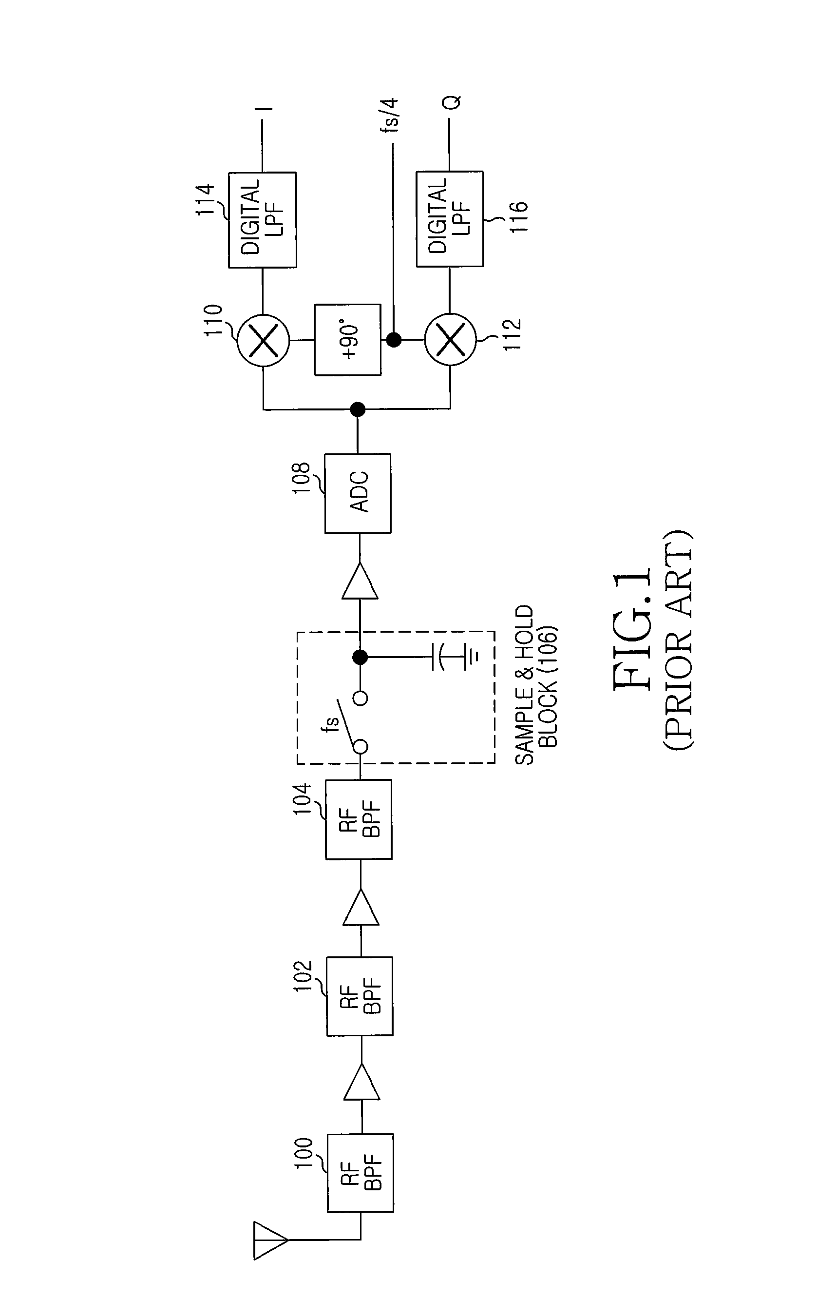
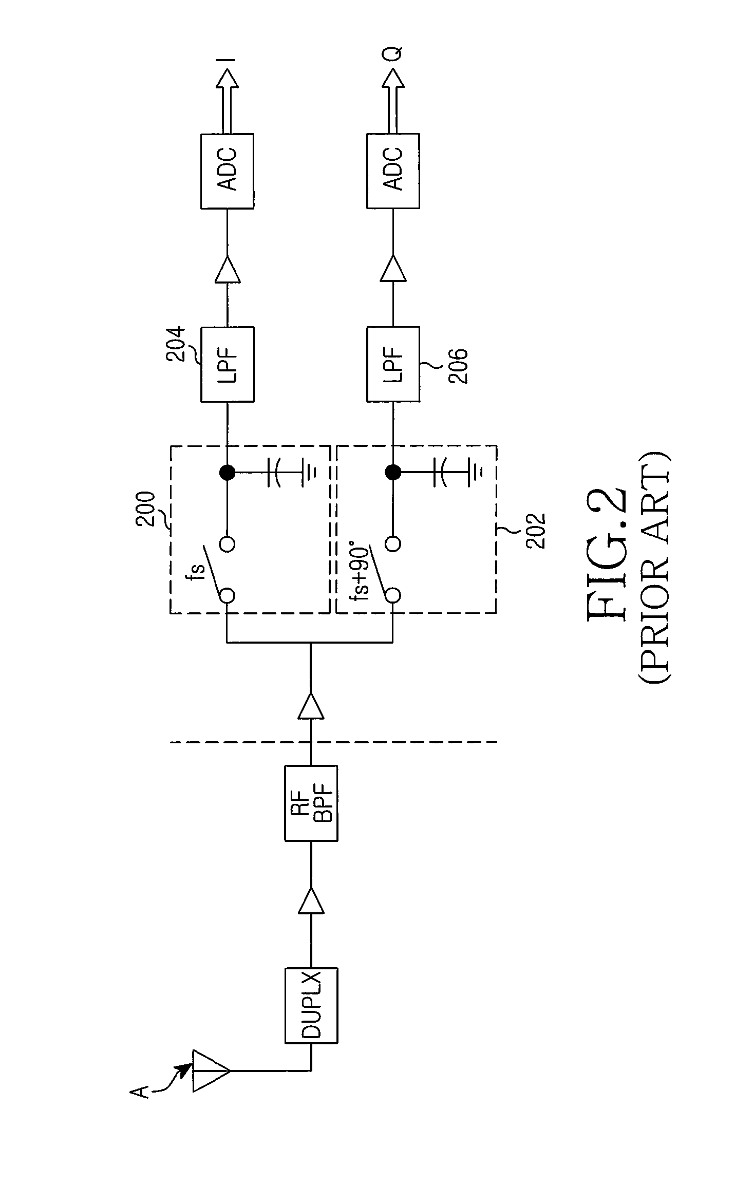
However, since the ADC is disposed in the IF stage and the RF stage uses the analog filters, these receivers lack flexibility for supporting the multiband multimode.
However, since the signal received via antenna is input directly to the ADC after passing through only a Low Noise Amplifier (LNA) and the RF BPF, the receivers of FIGS. 3 and 4 can remove interference signals outside the receive band but cannot remove an in-band blocker (interferer) in the receive band.
Hence, in terms of the power consumption of the ADC, the receiver structures of FIGS. 3 and 4 are not technically suitable for a terminal that is limited as to available power.

Method used


Image

  • Apparatus and operating method of digital RF receiver in a wireless communication system
  • Apparatus and operating method of digital RF receiver in a wireless communication system
  • Apparatus and operating method of digital RF receiver in a wireless communication system

Examples


Embodiment Construction

[0026]Various embodiments of the present invention are described in detail herein below with reference to the accompanying drawings. In the drawings, the same or similar components may be designated by the same or similar reference numerals, although they are illustrated in different drawings. Further, detailed descriptions of constructions or processes known in the art may be omitted for the sake of clarity and conciseness.

[0027]Embodiments of the present invention provide an apparatus and an operating method of a digital RF receiver for supporting multiband multimode in a wireless communication system.

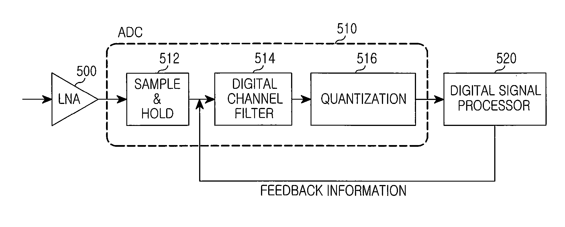
[0028]FIG. 5 illustrates a receiver structure in a wireless communication system according to the present invention.

[0029]Referring to FIG. 5, the receiver includes an LNA 500, an ADC 510, and a Digital Signal Processor (DSP) 520. The ADC 510 includes a sample and hold unit 512, a digital channel filter 514, and a quantization unit 516.

[0030]The LNA 500 low noise amplifies a signal r...


PUM


Abstract

An apparatus and an operating method of a digital Radio Frequency receiver in a wireless communication system are provided. The digital RF receiver includes a digital signal processor for outputting information of a receive frequency band, and an Analog-Digital Converter for filtering a signal of the receive frequency band from an RF analog signal input and converting the filtered signal to a digital signal.

Description

PRIORITY[0001]This application claims priority under 35 U.S.C.§119(a) to a Korean patent application filed in the Korean Intellectual Property Office on Feb. 24, 2009 and assigned Serial No. 10-2009-0015152, the contents of which are incorporated herein by reference.BACKGROUND OF THE INVENTION[0002]1. Field of the Invention[0003]The present invention relates generally to an apparatus and an operating method of a digital Radio Frequency (RF) receiver in a wireless communication system, and more particularly, to an apparatus and an operating method of a digital RF receiver for supporting a multiband multimode.[0004]2. Description of the Related Art[0005]Due to the recent proliferation of communication techniques, network operators have focused on providing an integrated receiver that can simultaneously support the various communication techniques. Such a receiver is known as a multiband receiver.[0006]A conventional receiver down-converts a Radio Frequency (RF) signal to an Intermedia...

Claims


Application Information

Patent Timeline
Patent Type & Authority Applications(United States)
IPC IPC(8): H04L27/00
CPCH04B1/1036H04B1/30H04L5/0064H04B1/0007H04L27/0002H04L27/0008H04L5/06H03M1/12H04B1/06
Inventor ZEONG, JONG-WOOKHWANG, SEON-HOCHOI, WON-SUKPARK, HAN-GUE
Owner SAMSUNG ELECTRONICS CO LTD
Learn More