Digital radio communication system for communicating M-ary modulated error detection units

a digital radio communication and error detection technology, applied in phase-modulated carrier systems, instruments, coding, etc., can solve the problems of difficult determination of reception signal point and likelihood calculation, deterioration of reception characteristics, etc., to improve error correction capability, improve reception characteristics, and high precision

Inactive Publication Date: 2006-01-24
PANASONIC CORP
View PDF23 Cites 71 Cited by
  • Summary
  • Abstract
  • Description
  • Claims
  • Application Information

AI Technical Summary

Benefits of technology

[0004]It is an object of the present invention to provide a digital radio communication system in which error correction capabi...

Problems solved by technology

However, with M-ary modulation there is a problem in that the greater the number of bits arranged in one symbol, the smaller is the signal point interval in th...

Method used


Image

  • Digital radio communication system for communicating M-ary modulated error detection units
  • Digital radio communication system for communicating M-ary modulated error detection units
  • Digital radio communication system for communicating M-ary modulated error detection units

Examples


embodiment 1

(Embodiment 1)

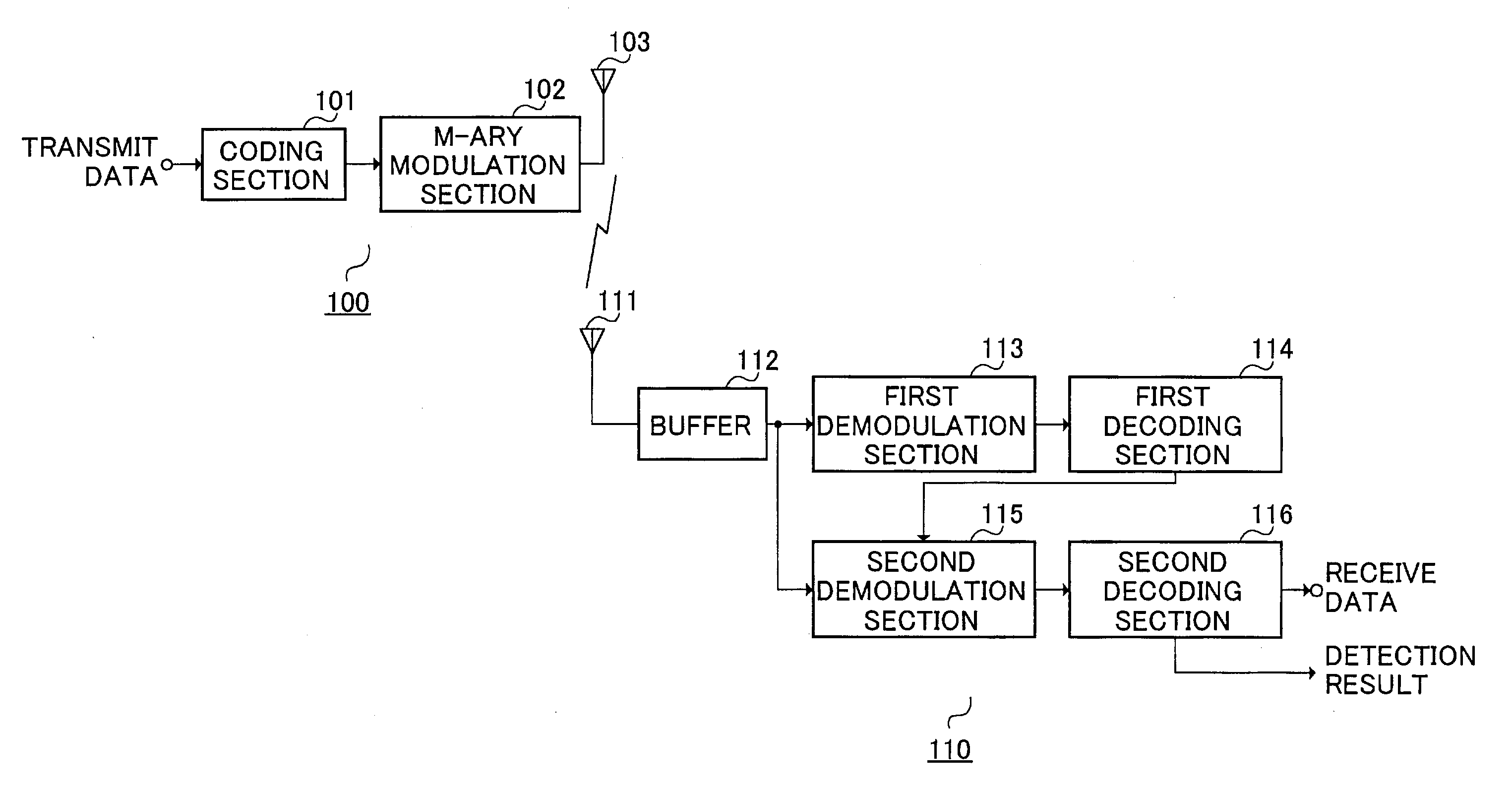
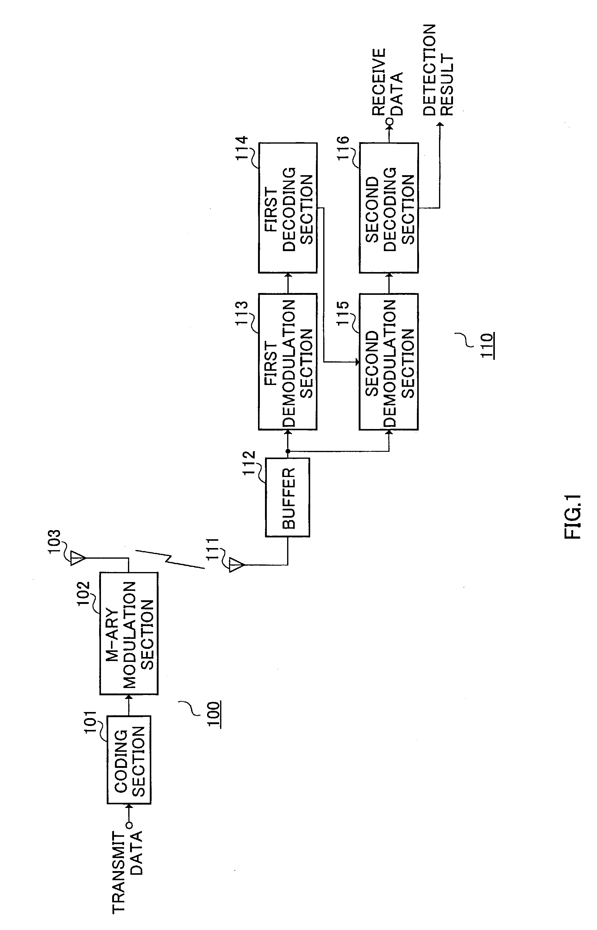
[0096]FIG. 1 is a block diagram showing the configuration of a radio communication system according to Embodiment 1 of the present invention. In the radio communication system shown in FIG. 1, radio communications are performed between a transmitting apparatus 100 and receiving apparatus 110. Unless indicated otherwise, in the following embodiments a case in which 8PSK is performed will be described by way of example.

[0097]In the transmitting apparatus 100, a coding section 101 performs error detection coding of transmit data for each predetermined error detection unit, and performs error correction coding for each predetermined error correction unit. An M-ary modulation section 102 performs M-ary modulation of the output signal from the coding section 101, and performs radio transmission of this signal from an antenna 103.

[0098]In the receiving apparatus 110, a signal received from an antenna 111 is first stored in a buffer 112, and then output to a first demodulation...

embodiment 2

(Embodiment 2)

[0124]Embodiment 2 of the present invention is a variant of Embodiment 1, and describes a case in which a plurality of error detection units are taken together as one error correction unit.

[0125]FIG. 6 is a block diagram showing the configuration of a radio communication system according to Embodiment 2 of the present invention. In the radio communication system shown in FIG. 6, radio communications are performed between a transmitting apparatus 200 and receiving apparatus 210. In the transmitting apparatus 200, the configuration of the coding section 201 differs from that of the coding section 101 shown in FIG. 1, and in the receiving apparatus 210, the first decoding section 214 and second decoding section 216 differ from the first decoding section 114 and second decoding section 116 shown in FIG. 1.

[0126]FIG. 7 is a block diagram showing the internal configuration of the coding section 201 of the transmitting apparatus 200 shown in FIG. 6. Parts in FIG. 7 identical ...

embodiment 3

(Embodiment 3)

[0132]Embodiment 3 of the present invention is a variant of Embodiment 1, and describes a case in which the number of independent error detection units contained in one symbol is made identical to the number of bits arranged in one symbol by providing error detection units that differ according to the bit position, and performing interleaving for each error detection unit.

[0133]FIG. 10 is a block diagram showing the configuration of a radio communication system according to Embodiment 3 of the present invention. In the radio communication system shown in FIG. 10, radio communications are performed between a transmitting apparatus 300 and receiving apparatus 310. In the transmitting apparatus 300, the configuration of the coding section 301 differs from that of the coding section 101 shown in FIG. 1, and in the receiving apparatus 310, the first decoding section 314 and second decoding section 316 differ from the first decoding section 114 and second decoding section 11...


PUM


Abstract

A coding section 101 performs error detection coding of data for each predetermined error detection unit, and an M-ary modulation section 102 arranges data belonging to a plurality of error detection units in one transmission unit, and transmits that data. A first decoding section 114 decodes a received signal, and performs error detection on the decoding result for each error detection unit. A second demodulation section 115 modifies the likelihood of each bit based on the result of error detection in the first decoding section 114. By this means, it is possible to improve the error correction capability of a signal that has undergone M-ary modulation using high-precision likelihoods, and to improve transmission quality.

Description

TECHNICAL FIELD[0001]The present invention relates to a digital radio communication system that uses M-ary modulation, and more particularly to a digital radio communication system that enables the demodulation characteristics of a signal modulated by M-ary modulation to be improved.BACKGROUND ART[0002]With the recent diversification of services, a demand has arisen for greater volumes of data to be transmitted in a downlink. To meet this demand, M-ary modulation is used, in which a plurality of bits are arranged in one symbol. M-ary modulation is a modulation method whereby a plurality of bits are arranged in one symbol. Widely-known M-ary modulation methods include QPSK, in which 2 bits are arranged in one symbol, 8PSK, in which 3 bits are arranged in one symbol, and 16QAM, in which 4 bits are arranged in one symbol.[0003]However, with M-ary modulation there is a problem in that the greater the number of bits arranged in one symbol, the smaller is the signal point interval in the ...

Claims


Application Information

Patent Timeline
IPC IPC(8): H04L1/18H03M13/03H04L27/18H04L1/00H04L27/22H04L27/34H04L27/38
CPCH04L1/005H04L1/0058H04L27/38H04L1/1635H04L1/1893H04L25/067H04L27/22H04L27/3405H04L1/0041H04L1/0061H04L1/007H04L1/0071H04B1/40H04L1/00
Inventor UESUGI, MITSURUMIYOSHI, KENICHI
Owner PANASONIC CORP
Why Eureka
Try Eureka