Long-distance wireless-lan directional antenna alignment

a technology of directional antennas and long-distance wireless lans, which is applied in the direction of antennas, antenna details, electrical equipment, etc., can solve the problems of increasing the cost of these system chipsets, and increasing the cost of these process steps. , to achieve the effect of ultra-low cost, ultra-low weight and low cos

Active Publication Date: 2010-09-23
SECURIFI INC
View PDF2 Cites 58 Cited by
  • Summary
  • Abstract
  • Description
  • Claims
  • Application Information

AI Technical Summary

Benefits of technology

[0018]The invention is “combination” or “unitized” device that combines the electronics for a normal or modified IEEE 802.11 (Wi-Fi), IEEE 802.15 or (Bluetooth) or 802.15.4) ultra low cost Wireless LAN or Wireless PAN chipset, along with a microprocessor, software, electronics to drive a directional antenna, and the motors and gearing necessary to physically move a directional antenna, into an ultra-low weight, and ultra-low cost assembly designed enable long-distance communications links to be established with both minimal cost and minimal time and skill on the part of the installers. In one embodiment, the software methods incorporated into the software of this unitized device can include methods necessary to automatically or semi-automatically configure and align the antenna with minimal user skill and effort.

Problems solved by technology

These devices originally assigned to the unlicensed frequency bands such as 2.4 GHz, 900 MHz and later in the 5 Gigahertz region and originally intended for ranges of up to only a few hundred feet, are now so prevalent that the costs for these system chipsets are now down to only a few dollars each.
One problem with setting up such modified or “hacked” IEEE 802.11 Wireless-LAN based long distance communications, however is that in order to allow what is essentially short-range equipment and standards to operate over far longer ranges than originally intended, the antennas (on both ends of the communications link) must be fairly large and highly directional.
At present, prior art methods often involve a tedious process in which an installer climbs onto the structure holding the antenna, talks via a mobile phone or a second set of two-way radios with a counterpart at the other end of the link, and the two manually adjust the antennas and assess the signal strength and signal quality of the link.
Additionally, regulatory requirements also require that these installers be qualified professionals, which adds additional cost to this process.
The end result is both dangerous to the workers, and not fully satisfactory under all conditions, because unless the structure that the directional antenna is bolted to is quite sturdy, with time the antenna alignment can drift to an unsatisfactory position.
Such drift in alignment would not only require a professional installer's service for alignment, but also cause down time to the network till the availability of such an installer.
Although prior art methods for automatically steering satellite antennas and other non-Wireless-LAN directional antennas, exemplified by U.S. Pat. Nos. 4,841,309, 5,214,364, 6,049,306, 6,850,202, 6,864,847, and 7,633,893 are known, these methods tend to be both elaborate and expensive, and are not well suited for the ultra-low cost demands of long distance telecommunications using modified or “hacked” versions of the IEEE 802.11 (Wi-Fi) standard, and its related standards such as 802.15 (Bluetooth) and 802.15.4 (Zigbee) standards.

Method used


Image

  • Long-distance wireless-lan directional antenna alignment
  • Long-distance wireless-lan directional antenna alignment
  • Long-distance wireless-lan directional antenna alignment

Examples


Embodiment Construction

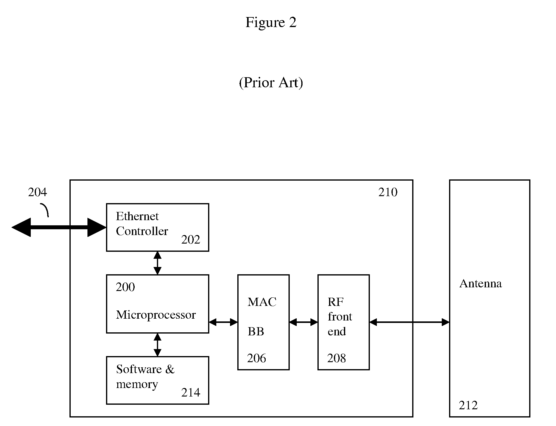
[0029]As previously discussed, this invention is designed for operation with ultra-low cost Wi-Fi, Bluetooth, or Zigbee chipsets, originally intended for short range digital signal transmission. Such chipsets are commercially available from a number of vendors, including Atheros, Broadcom, Intel and other companies.

[0030]Typically a number of changes must be made to the IEEE 802.11 standard in order to enable chipsets based upon this design to operate over longer distances. These changes include modifications to the ACK timeouts. This is because the standard 802.11 stop and wait “ACK” recovery settings works poorly when, due to longer distances and speed of light issues, propagation delays are longer. As used in this patent, the criteria for chipsets that are useful for the invention are chipsets that, with proper software or chipset firmware adjustments, are capable of implementing the IEEE 802.11 (Wi-Fi), IEEE 802.15 (Bluetooth), or IEEE 802.15.4 (Zigbee) standards. This definitio...


PUM


Abstract

A unitized device and method to optimize directional antenna alignment for long-distance communications using the low-cost IEEE 802.11 (and related) compatible RF-chipsets (originally designed for short range Wireless-LAN and Wireless-PAN networks). The device combines these chipsets, along with a microprocessor, software, electronics to drive a directional antenna, and the motors and gearing necessary to physically move a directional antenna, into a unitized low weight, and low cost assembly designed to enable reliable digital radio links of many miles or more to be established with minimal costs, time, and installer skill. In one embodiment, the software methods incorporated into the software of this unitized device can include methods necessary to automatically or semi-automatically configure and align the directional antenna to one or more distant target sources. Various mechanical designs, as well as various software and electronics methods, are also disclosed.

Description

CROSS REFERENCE TO RELATED APPLICATIONS[0001]This application claims the priority benefit of provisional application No. 61 / 162,132 “Automated Antenna Alignment for Long Range Wireless Devices”, filed Mar. 20, 2009.BACKGROUND OF THE INVENTION[0002]1. Field of the Invention[0003]The invention is in the general field of Wireless LAN and directional antenna alignment devices and methods.[0004]2. Description of the Related Art[0005]In recent years, a variety of high-speed short range digital radio transceiver devices, in particular wireless local area network (Wireless-LAN or WLAN) devices, and Wireless Personal Area Network (WPAN) devices have become ubiquitous in the modern world. These devices originally assigned to the unlicensed frequency bands such as 2.4 GHz, 900 MHz and later in the 5 Gigahertz region and originally intended for ranges of up to only a few hundred feet, are now so prevalent that the costs for these system chipsets are now down to only a few dollars each.[0006]The...

Claims


Application Information

Patent Timeline
Patent Type & Authority Applications(United States)
IPC IPC(8): H01Q3/02H01Q3/00
CPCH01Q1/125H01Q3/08H01Q1/2291
Inventor MALASANI, RAMMOHAN
Owner SECURIFI INC
Why Eureka
Try Eureka