Weighted mounting arrangement for, and method of, steadily supporting a motion-sensitive, image capture device
Inactive Publication Date: 2011-03-24
THE TIFFEN
View PDF2 Cites 38 Cited by
Summary
Abstract
Description
Claims
Application Information
AI Technical Summary
This helps you quickly interpret patents by identifying the three key elements:
Problems solved by technology
Method used
Benefits of technology
[0011]The base is advantageously provided with an insert having an internally threaded passage for threaded engagement with an externally threaded stud extending away from the support in the supported orientation during the image capture. The stud is preferably an industry standard 1/4 inch-20 threaded mounting stud to enable the mount to be readily mounted on industry standard camera and video equipment mounting platforms, such as tripods and/or handheld equipoising supports.
[0012]The base is also advantageously provided with an anti-rotation index hole for receiving an index pin extending away from the support in the supported orientation during the image capture. This
Problems solved by technology
Still picture and motion picture (video) cameras have, at some time during their use, been handheld by a human operator whose inherent instability tended to produce blurred still and moving images.
In addition to the traditional unsteadiness of a handheld camera, these handheld devices were being operated by amateur photographers, still further resulting in unstable and often unacceptable still and video images, especially during ambulatory operation.
Yet, the known handheld devices have not been directly integrated with the capability for such devices to be mounted onto industry standard camera and video equipment mounting platforms, such as tripods and/or equipoising supports.
Hence, this readily available industrial equipment cannot be used to help stabilize and/or manipulate the handheld devices.
As desirable as such adjustable mechanisms have been in non-image capture applications, they are
Method used
Image
Click on the blue label to locate the original text in one second.
Reading with bidirectional positioning of images and text.
Examples
Embodiment Construction
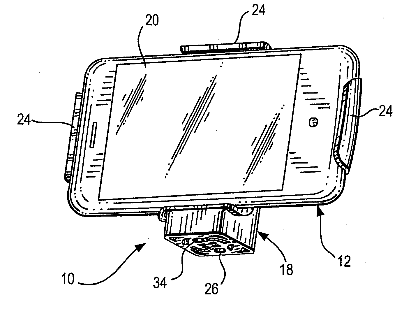
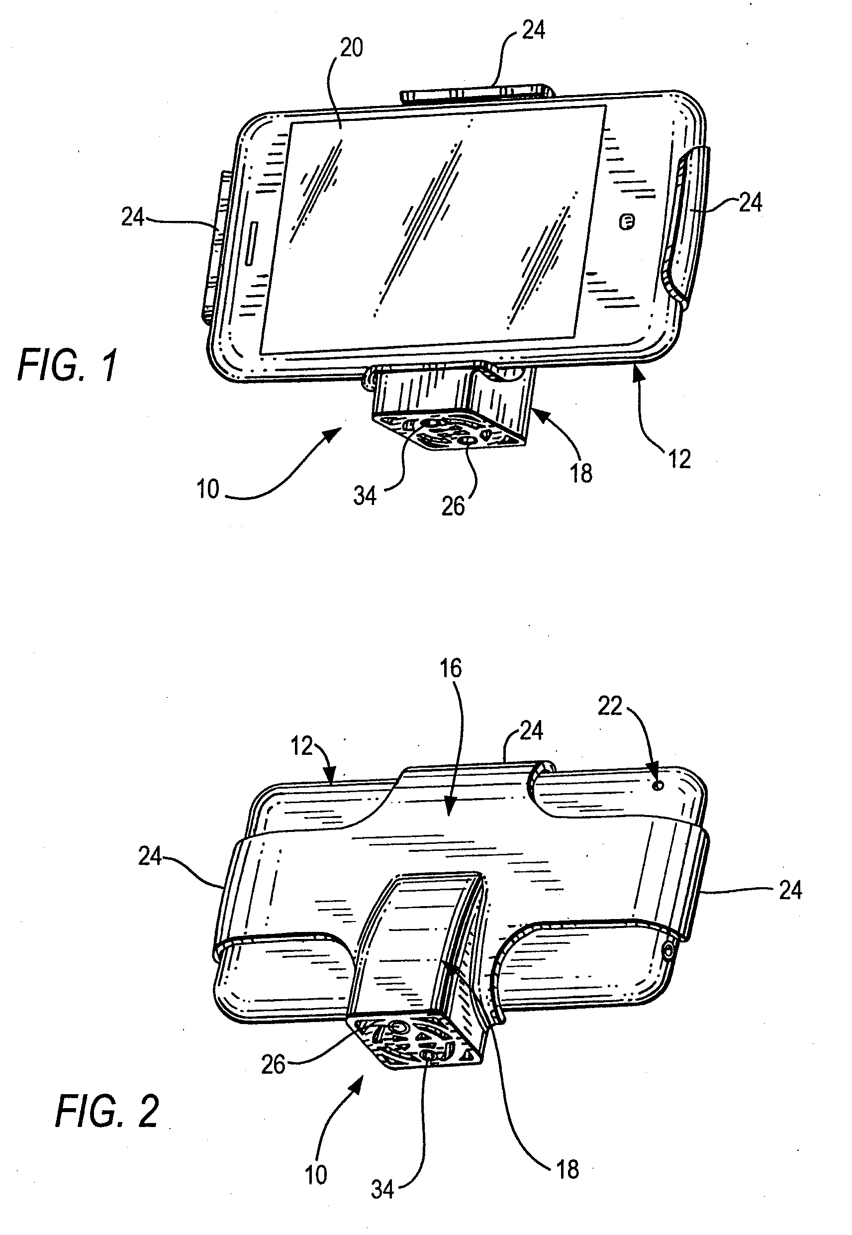
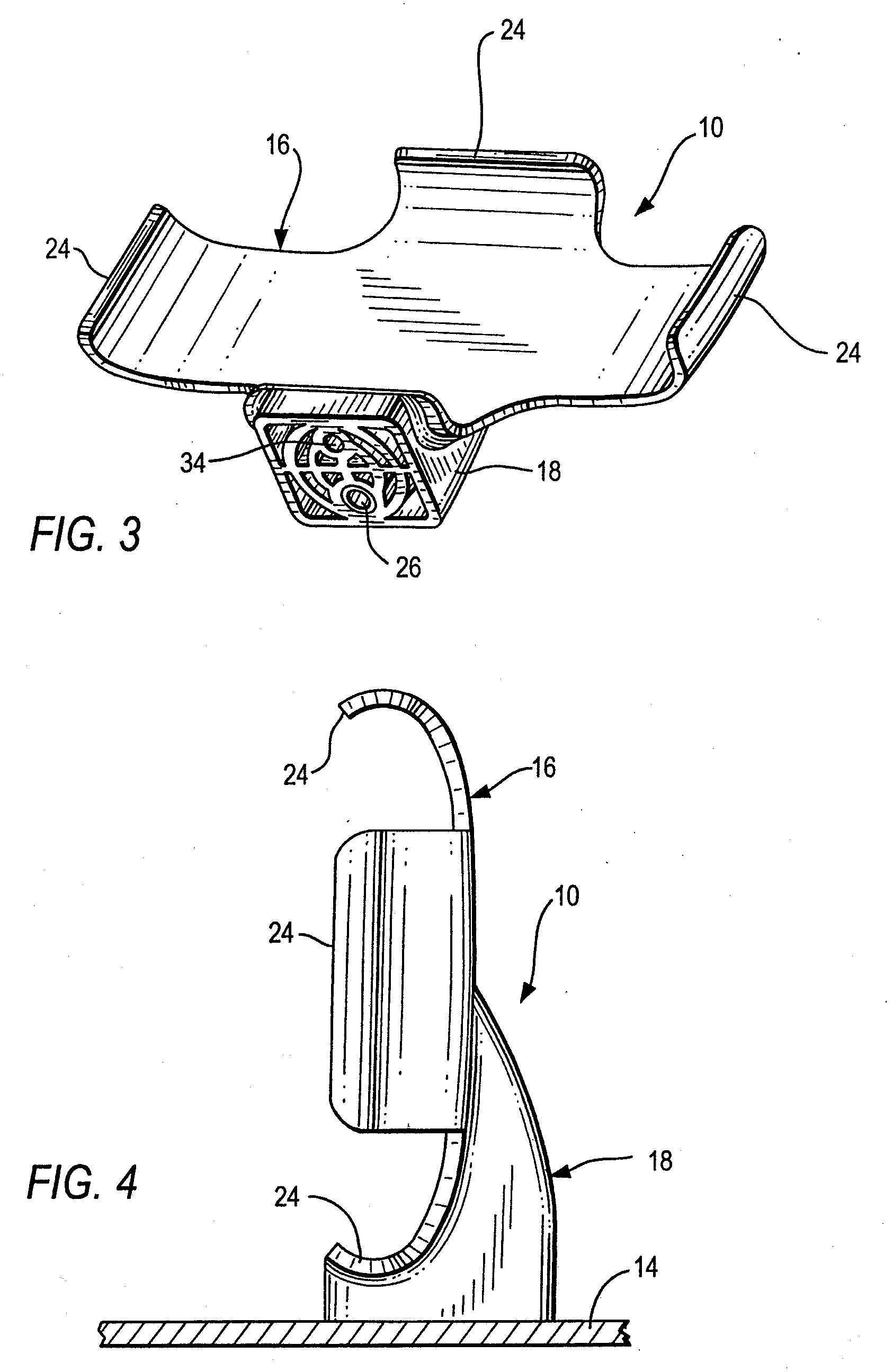
[0033]Referring now to the drawings, reference numeral 10 generally identifies a stabilized mount of a mounting arrangement for steadily and stably supporting a motion-sensitive, image capture device 12 on a support 14 (see FIGS. 4-7). The device 12 is operative for capturing an image over a field of view along an optical axis perpendicular to an image plane. The device 12 may be a stand-alone image capture device, e.g., an ultra-lightweight camera, a web camera, a camcorder, etc., or may be a multiple use device, such as a cellular telephone, a personal digital assistant, a media player, a game controller, and like devices in which image capture capability has been incorporated. The support 14 is preferably a handheld equipoising structure (FIGS. 7, 14 and 15), but may be a tripod (FIG. 5), or a table or countertop (FIG. 4).
[0034]As illustrated in FIGS. 1-2, the device 12 is an iPhone, which is a multimedia smartphone marketed by Apple, Inc. This device 12 has an internal solid-sta...
PUM
Abstract
A weighted mounting arrangement stably supports a motion-sensitive, image capture device incorporated in a cellular telephone. The arrangement includes a handheld equipoising structure having a platform and a handle connected to the platform at a handle connection, a mount on the platform for holding the device during image capture, and a ballast weight mounted on the mount with the held device as an assembly. The assembly and the equipoising structure together have a combined center of gravity positioned in close adjacent proximity below the handle connection for balancing the arrangement during image capture.
Description
[0001]This application is a continuation-in-part of U.S. patent application Ser. No. 12 / 508,873, filed Jul. 24, 2009, now pending.BACKGROUND OF THE INVENTION[0002]This invention generally relates to a weighted mounting arrangement for, and a method of, steadily supporting motion-sensitive, image capture devices, such as stand-alone image capture devices, e.g., ultra-lightweight cameras, web cameras and camcorders, as well as other multiple use devices, such as cellular telephones, personal digital assistants, media players, game controllers, and like devices in which image capture capability has been incorporated and, more particularly, relates to isolating all such devices from unwanted motion during image capture.[0003]Still picture and motion picture (video) cameras have, at some time during their use, been handheld by a human operator whose inherent instability tended to produce blurred still and moving images. In recent years, ultra-lightweight cameras, such as web cameras weig...
Claims
Application Information
Patent Timeline
Application Date:The date an application was filed.
Publication Date:The date a patent or application was officially published.
First Publication Date:The earliest publication date of a patent with the same application number.
Issue Date:Publication date of the patent grant document.
PCT Entry Date:The Entry date of PCT National Phase.
Estimated Expiry Date:The statutory expiry date of a patent right according to the Patent Law, and it is the longest term of protection that the patent right can achieve without the termination of the patent right due to other reasons(Term extension factor has been taken into account ).
Invalid Date:Actual expiry date is based on effective date or publication date of legal transaction data of invalid patent.