Optical communication transmission system and method for checking performance of optical communication transmission system

a transmission system and optical communication technology, applied in the direction of transmission monitoring, digital transmission, transmission monitoring/testing/fault-measurement systems, etc., can solve the problems of complicated technique regarding the transmission system and the transmission system, and the difficulty in designing the structure of the transmitter-receiver in accordance with the increase in operation speed

Active Publication Date: 2011-03-24
NEC CORP
View PDF0 Cites 13 Cited by
  • Summary
  • Abstract
  • Description
  • Claims
  • Application Information

AI Technical Summary

Problems solved by technology

If the signal speed is to be increased without improving the capacity of the transfer path, it becomes difficult to design the structure of the transmitte...

Method used


Image

  • Optical communication transmission system and method for checking performance of optical communication transmission system
  • Optical communication transmission system and method for checking performance of optical communication transmission system
  • Optical communication transmission system and method for checking performance of optical communication transmission system

Examples


Embodiment Construction

Hereinafter, exemplary embodiments of the invention will be described in detail by referring to the drawings.

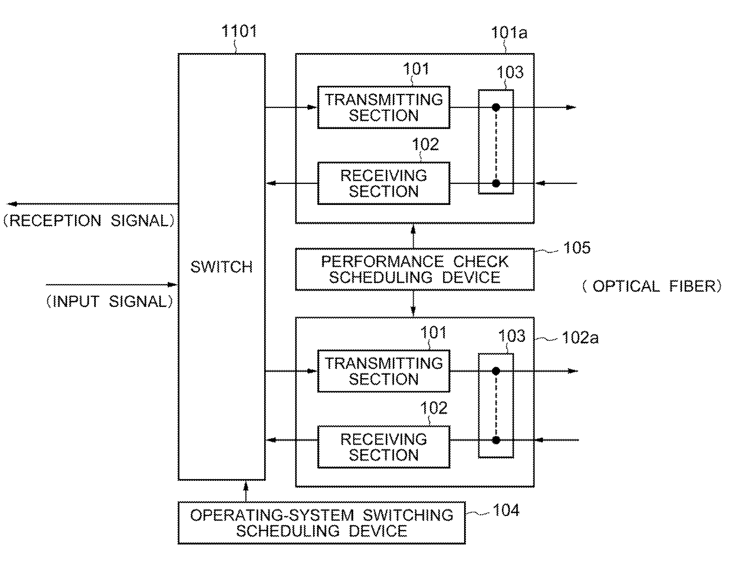
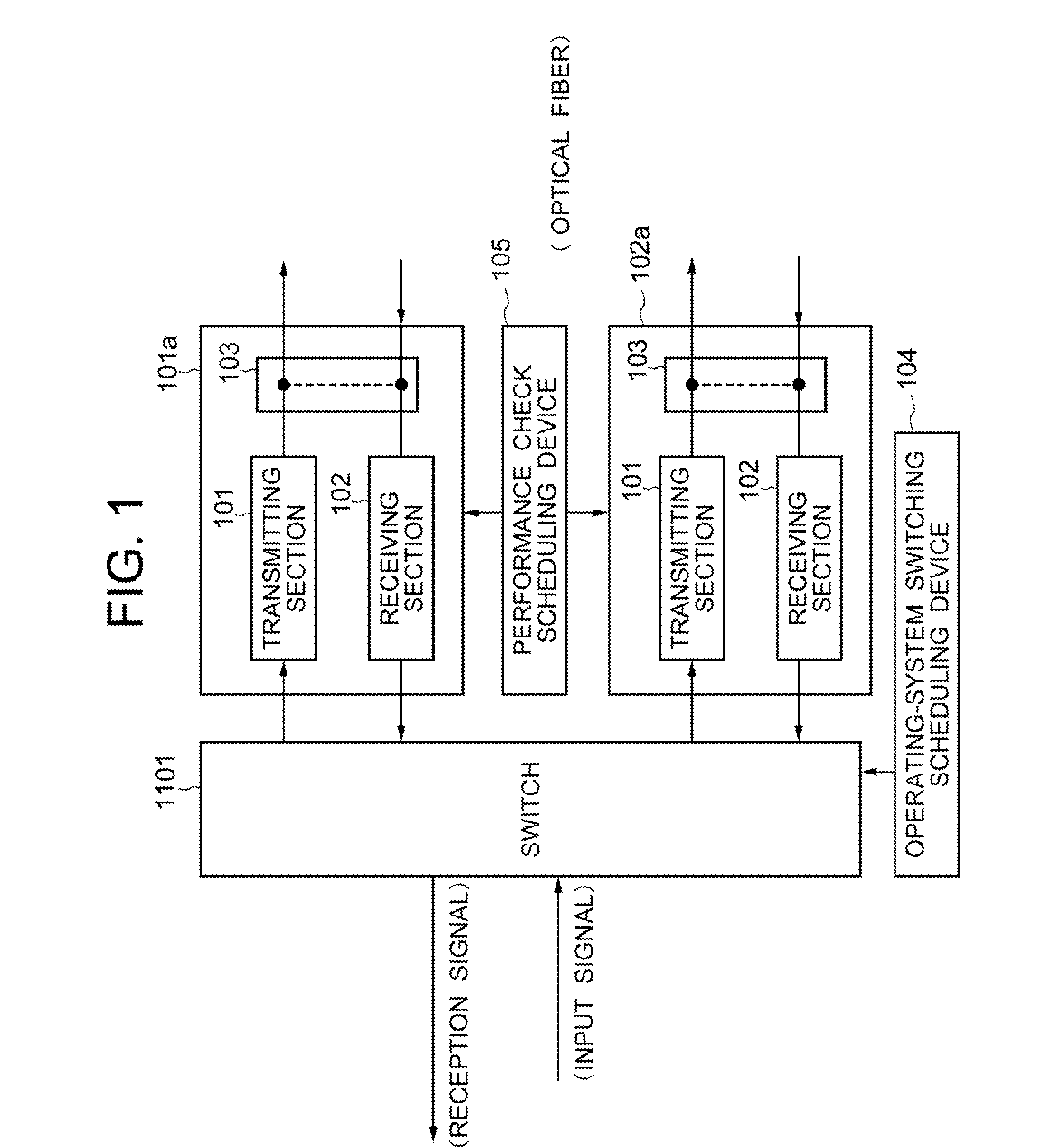
In order to detect the deterioration of the reliability after starting operations of an optical communication transmission system, two independent approaches are necessary. One is to establish a method for checking the performance of a transmitter-receiver. The other is to execute the established transmitter-receiver performance check method during the operation time. Each approach will be described hereinafter.

For checking the performance of the transmitter-receiver, it is the most typical and easiest way to use the signal light itself that has traveled from a distant place. For example, it is possible to predict changes in the performance to some extent from changes in the code error rate of the signal light after transmission, etc. However, when there is performance degradation, it is not possible with the method using the transmitted signal light to specify where (in the ...


PUM


Abstract

To detect the performance degradation of an optical communication transmission system after it becoming operational, thereby preventing the reliability of the system from lowering. In an optical communication transmission system, one of optical transmitter-receivers in a redundant-structured system is an active optical transmitter-receiver, and the other optical transmitter-receiver is a standby optical transmitter-receiver. The optical transmitter-receiver includes a loopback device through which the signal light of a transmitting section of the optical transmitter-receivers is inputted to a receiving section, and an operating-system switching scheduling device for regularly switching the operating system is provided. Further, there is also provided a performance check scheduling device which operates the loopback device of the standby-system optical transmitter-receiver at a prescribed timing determined in advance to start the performance check processing by the transmitting section and the receiving section of the optical transmitter-receiver.

Description

TECHNICAL FIELDThe present invention relates to an optical communication transmission system and a method for checking performances of the optical communication transmission system. More specifically, the present invention relates to an optical communication transmission system and a method for checking performances of the optical communication transmission system, which can increase the reliability by executing detection of performance degradation even after optical transmitter-receivers are being employed.BACKGROUND ARTAn optical communication transmission system which uses an optical fiber as a transmission path medium carries out an important role in a backbone communication network based on its long-distance transmission capability and large-volume transmission capability.As one of the indicators for the economical efficiency of the optical communication transmission system, there is a way of determining it based on how many transmission signals can be shared with an optical fi...

Claims


Application Information

Patent Timeline
IPC IPC(8): H04B10/08H04B10/035H04B10/073
CPCH04B1/74H04L27/2096H04B10/073H04B10/035
Inventor ITO, TOSHIHARU
Owner NEC CORP
Why Eureka
Try Eureka