Gasifier ash processing subsystem

a gasifier and ash processing technology, applied in the direction of gas modification by gas mixing, hydrogen, soldering iron, etc., can solve the problems of reducing the efficiency of non-fuel “clinkers, affecting the flow of gas, dangerous “updraft” condition, etc., to reduce or eliminate clinkers and minimize the waste of feedstock

Active Publication Date: 2011-03-31
MSW POWER
View PDF24 Cites 9 Cited by
  • Summary
  • Abstract
  • Description
  • Claims
  • Application Information

AI Technical Summary

Benefits of technology

[0006]One aspect of the subject invention is to provide a gasifier with a new grate subsystem. In some examples, such a grate subsystem can reduce or eliminate clinkers and / or better maintain the correct pressure drop along the reactor. Preferably, the new grate subsystem properly contains the fuel feedstock and minimizes any waste of the feedstock.
[0007]In some examples, the new grate subsystem is fairly simple in design. It is also an object of the subject invention, in one embodiment, to provide such a new grate subsystem which reduces or eliminates the need to manually clear the grate of clinkers. One preferred grate subsystem better maintains the proper flow of gas through the gasifier.
[0010]In one example, the sensor is a pressure sensor responsive to the pressure below the grate subsystem. In one version, the grate subsystem includes at least two downwardly angled fixed grates defining a hopper area between the grates. The grinding mechanism then typically includes at least two spaced grinding shafts disposed in the hopper area. In one particular example, each shaft includes a gear meshed with a gear on the other shaft to drive the shafts together. A motor drives one shaft and the controller is configured to energize the motor.

Problems solved by technology

Such non-fuel products collect on the gasifier grate and impede the flow of gas through the gasifier.
If the pressure drop along the reactor increases significantly, the result can be a dangerous “updraft” condition.
Known shaking or other grates are ineffective at removing the non-fuel “clinkers” which collect on the grates.
And, making the grate openings larger in size so that the clinkers pass through the grate considerably reduces yield because it allows for large, not fully converted feedstock to pass through.
This defeats the purpose of the grate.
Manually cleaning the grates of clinkers is inefficient as well since the gasifier must be shut down in order to do so.

Method used


Image

  • Gasifier ash processing subsystem
  • Gasifier ash processing subsystem
  • Gasifier ash processing subsystem

Examples


Embodiment Construction

[0027]Aside from the preferred embodiment or embodiments disclosed below, this invention is capable of other embodiments and of being practiced or being carried out in various ways. Thus, it is to be understood that the invention is not limited in its application to the details of construction and the arrangements of components set forth in the following description or illustrated in the drawings. If only one embodiment is described herein, the claims hereof are not to be limited to that embodiment. Moreover, the claims hereof are not to be read restrictively unless there is clear and convincing evidence manifesting a certain exclusion, restriction, or disclaimer.

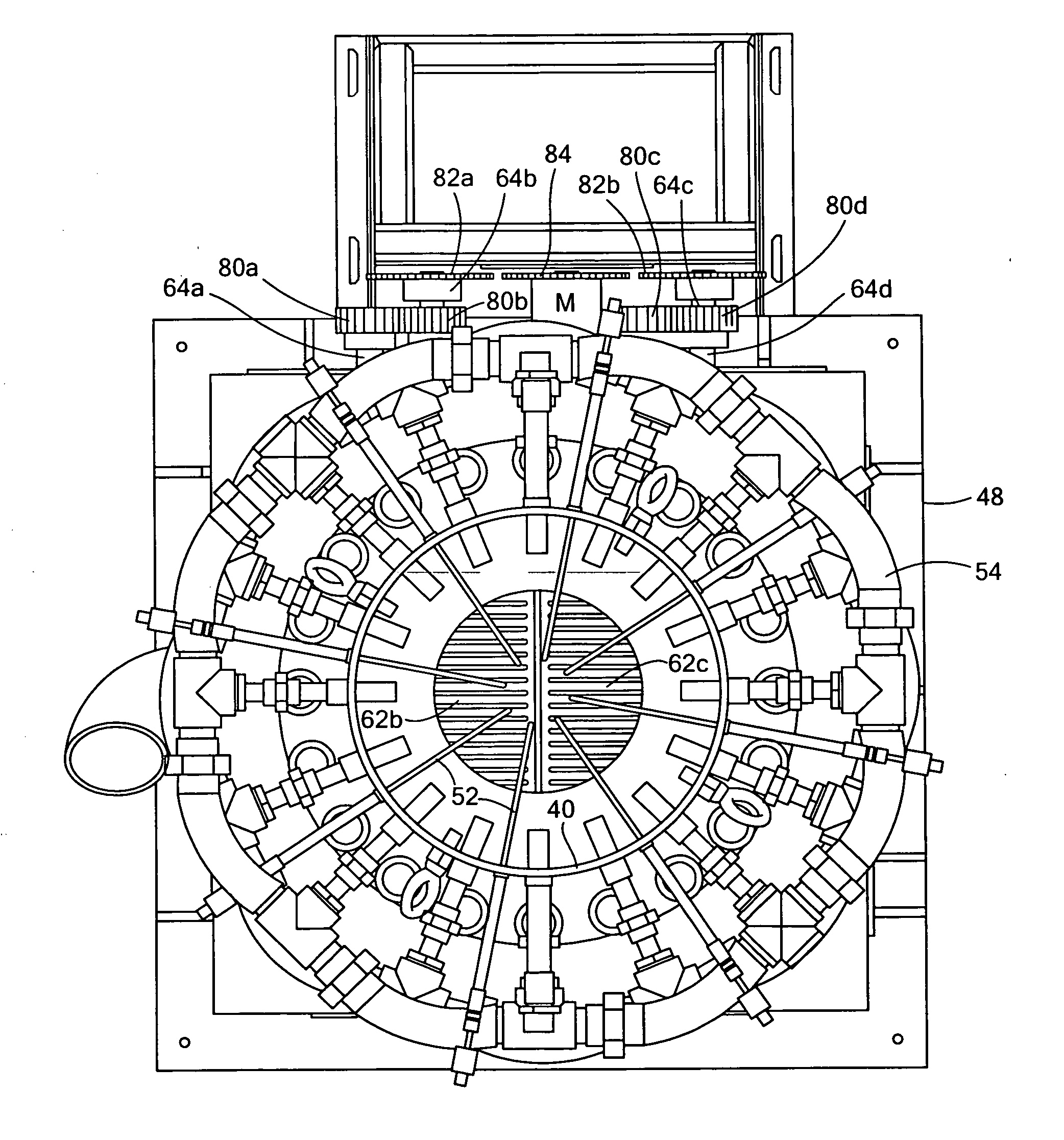
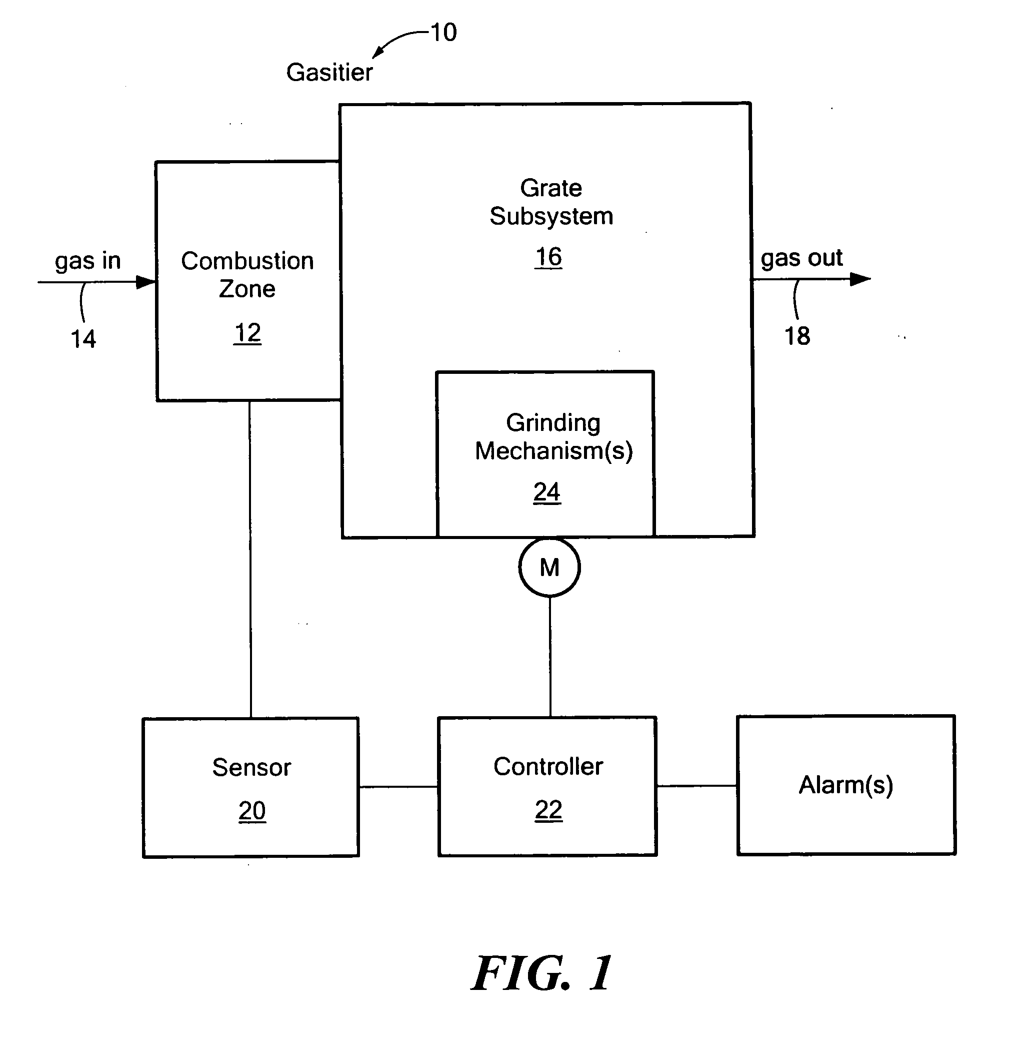
[0028]FIG. 1 shows a gasifier 10 according to an example of the subject invention including combustion zone 12 where an oxidizer such as air is introduced as shown at 14 and where fuel is combusted. Grate subsystem 16 contains (e.g., supports) the fuel bed. The gas output of the gasifier as shown at 18 may be used, after co...


PUM

PropertyMeasurementUnit
angleaaaaaaaaaa
angleaaaaaaaaaa
thickaaaaaaaaaa

Abstract

A gasifier includes a combustion zone where a gas is introduced and fuel is combusted and at least one sensor for measuring a predetermined condition in the gasifier. A grate subsystem contains the fuel and includes at least one grinding mechanism. A controller is responsive to the at least one sensor and controls the grinding mechanism by activating the grinding mechanism if the predetermined condition exists to reduce the collection of non-fuel products on the grate subsystem.

Description

FIELD OF THE INVENTION[0001]The subject invention relates to gasifier systems and, in one particular example, gasifiers used in waste-to-energy systems.BACKGROUND OF THE INVENTION[0002]A typical gasifier includes a combustion zone for fuel (e.g., pellets) and a grate supporting the fuel bed during combustion. Ash falls through the grate and is collected in some fashion. When the fuel is of a predetermined composition, the grate can be very simple in design, e.g., a plate with holes or slots in it. Those skilled in the art have also devised rotating grates and grates which shake in order to encourage the ash to fall through the grate. See “State of the Art for Small Scale Gas Producer-Engine Systems” by Ali Kaupp first published by the German Appropriate Technology Exchange and reissued by the Biomass Energy Foundation Press, Golden, Colo. 80401 incorporated herein by this reference.[0003]The applicant's co-pending application U.S. patent application Ser. No. 12 / 070,032 filed Feb. 14...

Claims


Application Information

Patent Timeline
Patent Type & Authority Applications(United States)
IPC IPC(8): C10J3/72C10J3/46
CPCC10J3/34C10J3/36F23G5/002F23G5/50F23G2207/102C10J2300/0916C10J2300/0956C10J2300/1625F23H13/08
Inventor YOUNG, MATTHEWANTHONY, STEVENARMSTRONG, STEPHENCHASE, STEVEN
Owner MSW POWER
Why Eureka
Try Eureka