Refrigeration system having a variable speed compressor

a compressor and variable speed technology, applied in refrigerators/freezers, domestic cooling devices, lighting and heating devices, etc., can solve the problems of inability of systems of this type to achieve uniform temperature, limited efficiency of operating such systems, and inefficiency, and achieve uniform temperature distribution

Active Publication Date: 2011-03-31
THERMO FISHER SCI ASHEVILLE
View PDF56 Cites 42 Cited by
  • Summary
  • Abstract
  • Description
  • Claims
  • Application Information

AI Technical Summary

Benefits of technology

[0016]The system disclosed herein is, accordingly, capable of attaining a relative long life expectancy, operating in an efficient manner, and attaining a uniform temperature distribution in the coo...

Problems solved by technology

In this regard, operation of the system may entail simply activating and deactivating each of the two compressors at various times. The ability of systems of this type to attain a uniform temperature in the cooled space, however, is limited, and the efficiency of operating such systems is also limited, as is the life expectancy of the systems themselves.
In addition, op...

Method used


Image

  • Refrigeration system having a variable speed compressor
  • Refrigeration system having a variable speed compressor
  • Refrigeration system having a variable speed compressor

Examples


Embodiment Construction

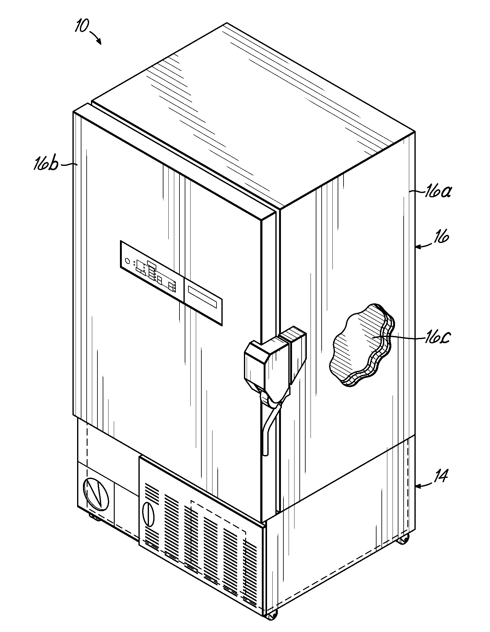
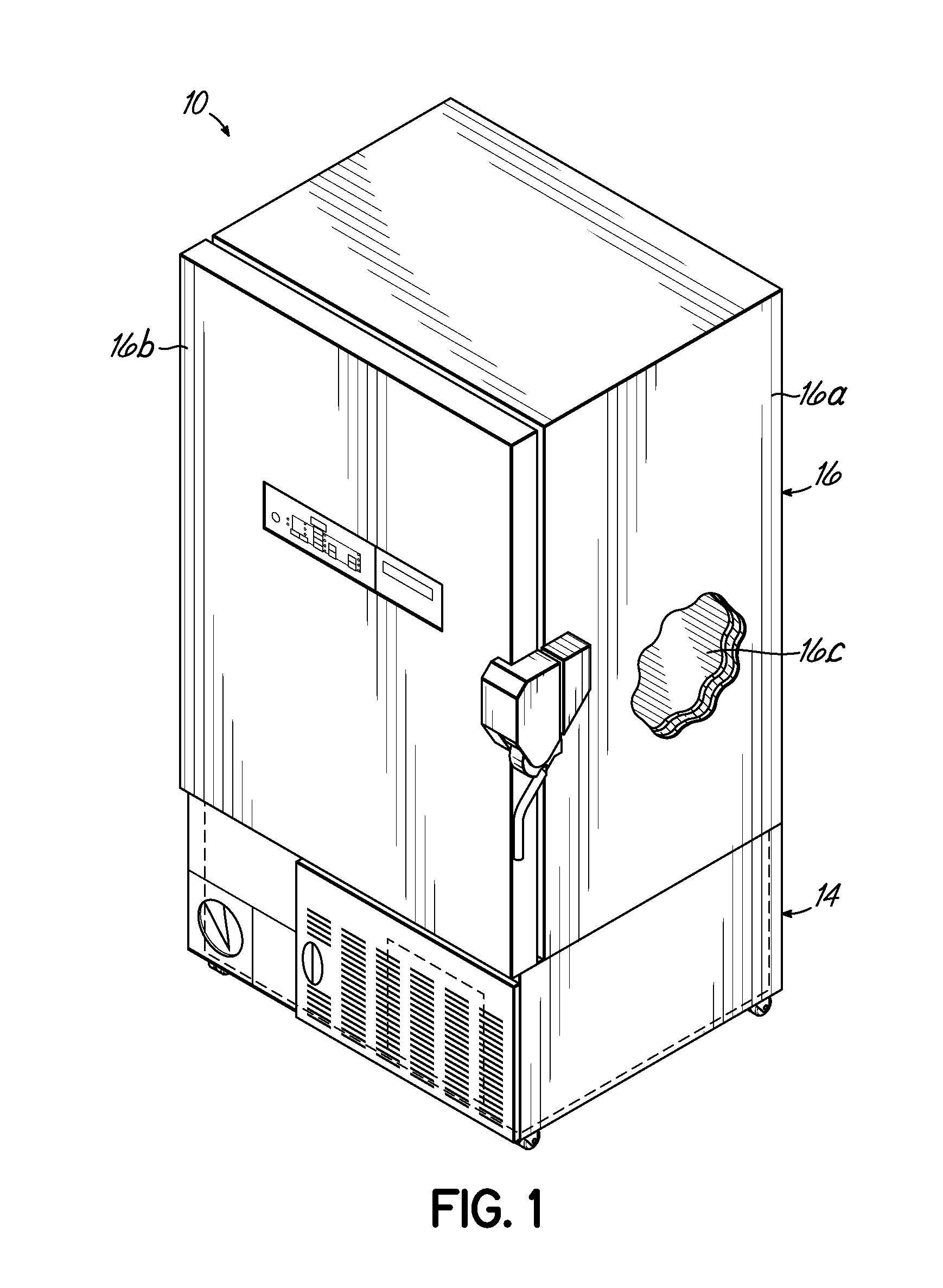
[0023]With reference to the figures, and more specifically to FIG. 1, a refrigeration unit in the form of an ultra-low temperature freezer (“ULT”) 10 is illustrated. Various aspects of the exemplary freezer 10 according to one embodiment of the present invention are described and illustrated in commonly assigned U.S. patent application Ser. No. ______ assigned to the assignee of the present application, entitled REFRIGERATION SYSTEM MOUNTED WITHIN A DECK (Attorney Docket TFLED-227AUS), the disclosure of which is hereby expressly incorporated by reference herein in its entirety.

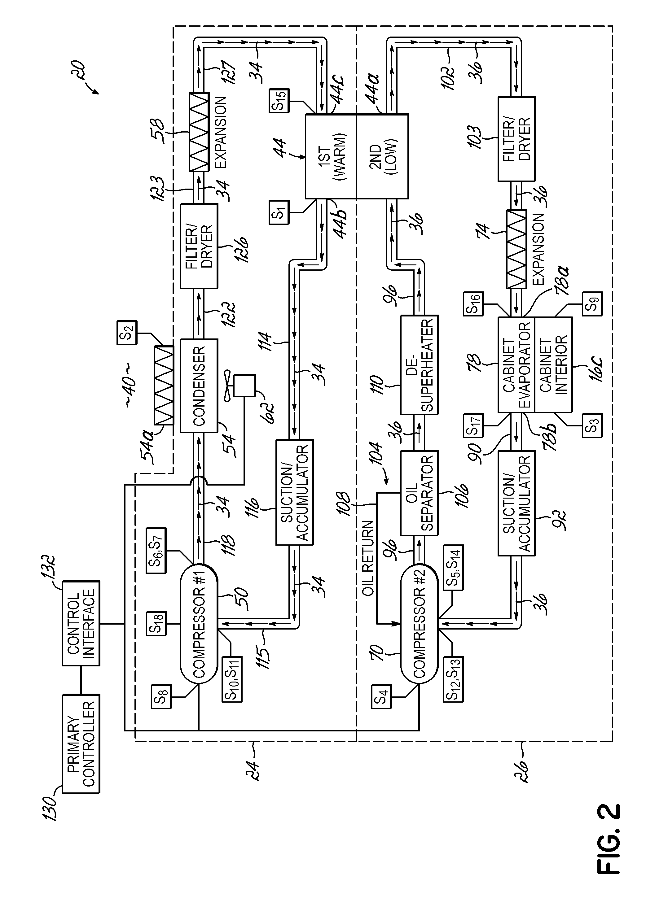
[0024]The freezer 10 of FIG. 1 includes a deck 14 that supports a cabinet 16 thereabove, for storing items that require cooling to temperatures of about −80° C. or lower, for example. The cabinet 16, in turn, includes a cabinet housing 16a and a door 16b providing access into an interior 16c of the cabinet 16. The deck 14 supports one or more components that jointly define a two-stage cascade refrigeration sys...


PUM


Abstract

A two-stage cascade refrigeration system is provided having a first refrigeration stage and a second refrigeration stage. The first refrigeration stage defines a first fluid circuit for circulating a first refrigerant, and has a first compressor, a condenser, and a first expansion device that is in fluid communication with the first fluid circuit. The second refrigeration stage defines a second fluid circuit for circulating a second refrigerant, with the second refrigeration stage having a second compressor, a second expansion device, and an evaporator that is in fluid communication with the second fluid circuit. A heat exchanger is in fluid communication with the first and second fluid circuits to exchange heat between the first and second refrigerants. At least one of the first or second compressors is a variable speed compressor.

Description

FIELD OF THE INVENTION[0001]The present invention relates generally to refrigeration systems and, more particularly, to two-stage cascade refrigeration systems.BACKGROUND OF THE INVENTION[0002]Two-stage cascade refrigeration systems are known for cooling spaces such as the interior of cabinets, for example, to temperatures well below zero degrees centigrade, such as temperatures below −40° C., for example. For example, freezers of the type known as ultra-low temperature freezers (“ULT's”) are known to use this type of refrigeration system and are used cool cabinet interiors to temperatures as low as about −80° C. or even lower.[0003]Refrigeration systems of this type are known to include two stages circulating respective first and second refrigerants. The first stage transfers energy (i.e., heat) from the first refrigerant to the surrounding environment through a condenser, while the second refrigerant of the second stage receives energy from the cooled space (e.g., a cabinet interi...

Claims


Application Information

Patent Timeline
IPC IPC(8): F25B7/00F25B1/10F25B41/00F25B39/04F25D19/00F25B1/00
CPCF25B7/00Y02B40/32F25B2500/12F25B2600/0253F25B2600/111F25B2700/1931F25B2700/1933F25B2700/21151F25B2700/21152F25B2700/21161F25B2700/21174F25B2700/21175F25D11/04F25D2700/02F25D2700/12F25D2700/14Y02B30/741Y02B30/743F25B49/022F25B2500/26Y02B30/70Y02B40/00
Inventor WANG, QISWIFT, TODDBAIR, RICHARD
Owner THERMO FISHER SCI ASHEVILLE
Why Eureka
Try Eureka