Blow-by gas refluxing device

Active Publication Date: 2011-03-31
AISAN IND CO LTD
View PDF8 Cites 39 Cited by
  • Summary
  • Abstract
  • Description
  • Claims
  • Application Information

AI Technical Summary

Benefits of technology

[0010]A blow-by gas refluxing device is provided for an engine system including an engine and an intake air passage communicating with the engine for supplying intake air into the engine. The blow-by gas refluxing device includes a plurality of blow-by gas refluxing passages each having an inlet communicating with the engine and an outlet communicating with the intake air passage. The outlets of the

Problems solved by technology

It has been known that in an engine installed on an automobile or the like, blow-by gas may be leaked from a combustion chamber to a crankcase through a gap between a piston and a cylinder and may deteriorate engine oil contained in the engine.
However, according to the technique of the above publication, when the pressure

Method used


Image

  • Blow-by gas refluxing device
  • Blow-by gas refluxing device
  • Blow-by gas refluxing device

Examples


Example

First Example

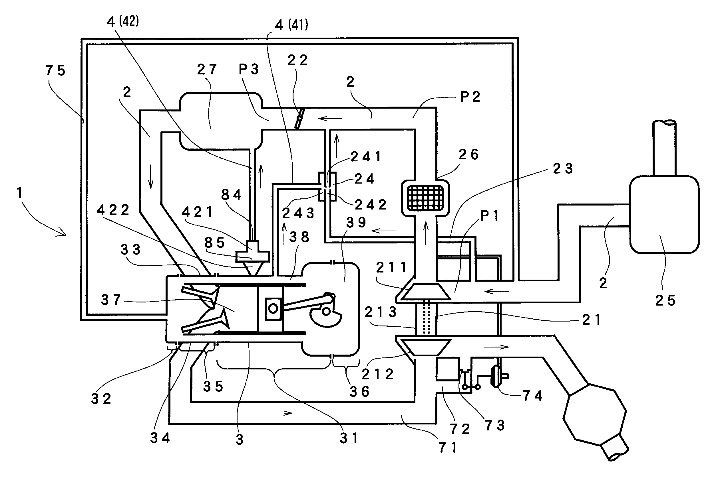
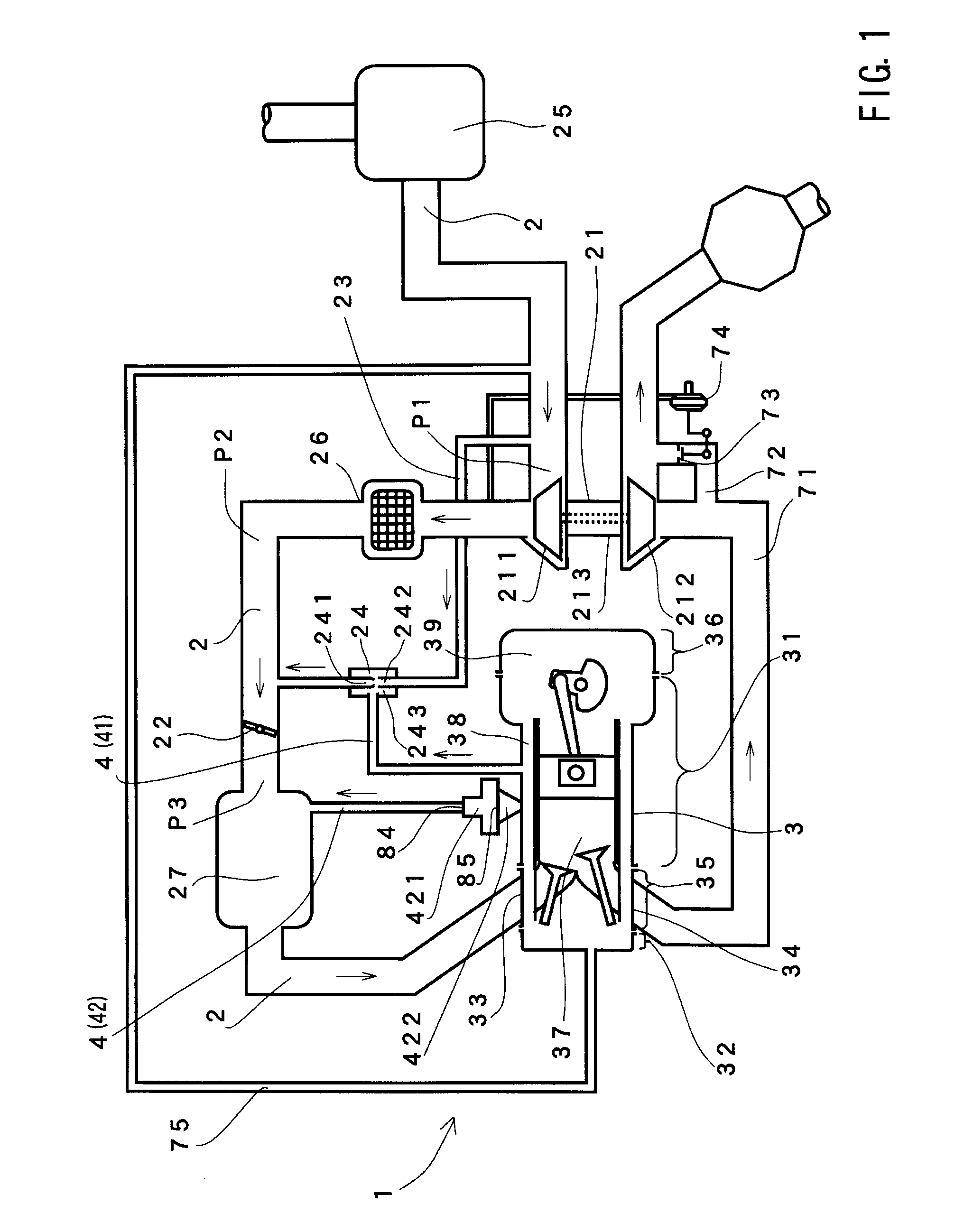
[0081]A first example t of a blow-by gas refluxing device will be explained referring to FIG. 1. FIG. 1 is a schematic view of an engine system including a blow-by gas refluxing device 1.

[0082]As shown in FIG. 1, the blow-by gas refluxing device 1 is provided for an engine 3 having a supercharger 21 and a throttle valve 22 arranged downstream of the supercharger 21 in an intake air passage 2. The blow-by gas refluxing device 1 is provided with a blow-by gas refluxing passage 4 that refluxes blow-by gas generated by the engine 3 to the engine 3 via the intake air passage 2. The blow-by gas refluxing device 1 is further provided with an intake air bypass passage 23 that communicates with the intake air passage 2 at the upstream and the downstream of the supercharger 21.

[0083]The blow-by gas refluxing passage 4 is provided with a first blow-by gas refluxing passage 41 and a second blow-by gas refluxing passage 42. The inlet of first blow-by gas refluxing passage 41 is conn...

Example

Second Example

[0125]As shown in FIG. 5, in a blow-by gas refluxing device 102 of this embodiment, the blow-by gas refluxing passage 4 of the first example is replaced with a blow-by gas refluxing passage 5 including a first blow-by gas refluxing passage 51 and a second blow-by gas refluxing passage 52 having an outlet connected to the first blow-by gas refluxing passage 51. The second blow-by gas refluxing passage 52 has a check valve 521 as a second backflow prevention device that prevents flow of the blow-by gas from the second blow-by gas refluxing passage 52 into the first blow-by gas refluxing passage 51. Further, on the upstream side of the check valve 521, an orifice 522 is provided as a blow-by gas flow rate restricting device which restricts the flow rate of the blow-by gas flowing into the second blow-by gas refluxing passage 52. The other constitution is the same as the first example.

[0126]According to the blow-by gas refluxing device 102 of this embodiment, the number of...

Example

Third Example

[0133]As can be seen in FIG. 7, in a blow-by gas refluxing device 103 of a third example, a vacuum switching valve (hereinafter called “VSV”) 61 is provided in the intake air bypass passage 23 of the second example, and the VSV 61 is controlled according to the condition of the engine 3 by an electronic control unit (hereinafter called “ECU”) 62. The other constitution is the same as the second example.

[0134]Values, such as a rotational speed of the engine 3 and the pressure of the intake air, may be detected by various sensors (not shown) arranged at the engine 3 and are input to the ECU 62, and the ECU 62 controls VSV 61 based on the detected values. The VSV 61 may be called an opening and closing valve.

[0135]FIG. 8 shows a flowchart of a control program executed by the ECU 62. When the process is passed to this routine, the ECU 62 first determines in Step 100 (S100) whether or not a predetermined time has passed after starting the engine 3. If the result of determina...


PUM


Abstract

A blow-by gas refluxing device is provided for an engine system including an engine and an intake air passage communicating with the engine for supplying intake air into the engine. The blow-by gas refluxing device includes a plurality of blow-by gas refluxing passages each having an inlet communicating with the engine and an outlet communicating with the intake air passage. The outlets of the blow-by gas passages communicate with the intake air passage at different positions along the length of the intake air passage and each of the blow-by gas passages has a backflow preventing device disposed therein, so that blow-by gas produced in the engine can flow into the intake air passage via at least one of the blow-by gas refluxing passages throughout the entire operational range of the engine.

Description

[0001]This application claims priority to Japanese patent application serial numbers 2009-227381 and 2009-250541, the contents of which are incorporated herein by reference.BACKGROUND OF THE INVENTION[0002]1. Field of the Invention[0003]The present invention relates to a blow-by gas refluxing device provided in an engine system having an engine, an intake air passage and a supercharger disposed in the intake air passage. The blow-by gas refluxing device refluxes blow-by gas, which is generated in the engine, to the engine through the intake air passage.[0004]2. Description of the Related Art[0005]It has been known that in an engine installed on an automobile or the like, blow-by gas may be leaked from a combustion chamber to a crankcase through a gap between a piston and a cylinder and may deteriorate engine oil contained in the engine.[0006]A technique relating to a blow-by gas refluxing device that ventilates blow-by gas leaked into a crankcase is reported in Japanese Laid-Open Ut...

Claims


Application Information

Patent Timeline
IPC IPC(8): F02B25/06
CPCF01M13/022F01M2013/026F01M13/021F01M13/028
Inventor HATTORI, MAKOTOKONOHARA, HIROKAZUONOBAYASHI, MINORU
Owner AISAN IND CO LTD
Why Eureka
Try Eureka