Hydraulic Circuit and Manifold with Multifunction Valve

a multi-functional valve and hydraulic circuit technology, applied in the field of hydraulic fluid manifolds, can solve the problems of increasing the complexity of the circuit, affecting weight, packaging, cost, and manufacturability, and achieve the effect of reducing the necessary number of valve mechanisms

Inactive Publication Date: 2011-03-31
THE UNITED STATES OF AMERICA AS REPRESENTED BY THE ADMINISTATOR OF THE U S ENVIRONMENTAL PROTECTION AGENCY EPA
View PDF7 Cites 17 Cited by
  • Summary
  • Abstract
  • Description
  • Claims
  • Application Information

AI Technical Summary

Benefits of technology

[0020]It is another object of the invention to minimize the necessary number of valve mechanisms in a vehicular hydraulic manifold ...

Problems solved by technology

These auxiliary functions may also require additional flow regulating means such as auxiliary pumps, check valves or proportional valves, adding to the complexity of the circuit.
Vehicular applications are also particularly sensitive to issues that affect weight, packaging, cost, and manufacturability.
The hydraulic manifold art has yet to develop standard solutions for these needs.
The design of a low pressure manifold for a vehicular application therefore remains a challenging and inventive task.
For example, if a blow-off event were to suddenly occur, the filter and coolers may fail or rupture before the control system has time to detect and respond to the condition by fully opening the proportional valves.
As another example, when a regenerative braking event occurs, a slow response might cau...

Method used


Image

  • Hydraulic Circuit and Manifold with Multifunction Valve
  • Hydraulic Circuit and Manifold with Multifunction Valve
  • Hydraulic Circuit and Manifold with Multifunction Valve

Examples


Embodiment Construction

[0040]Additional background regarding hydraulic hybrid vehicles may be found in U.S. Pat. No. 7,456,509 entitled METHODS OF OPERATING A SERIES HYBRID VEHICLE; U.S. Pat. No. 6,876,098 entitled METHODS OF OPERATING A SERIES HYBRID VEHICLE; U.S. Pat. No. 6,719,080 entitled HYDRAULIC HYBRID VEHICLE; and U.S. Pat. No. 5,495,912 entitled HYBRID POWERTRAIN VEHICLE; all issued to applicant and incorporated herein by reference in their entireties.

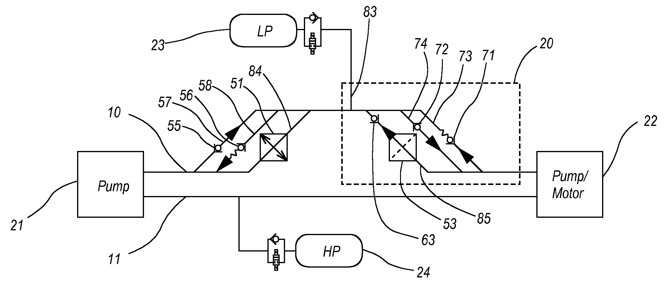
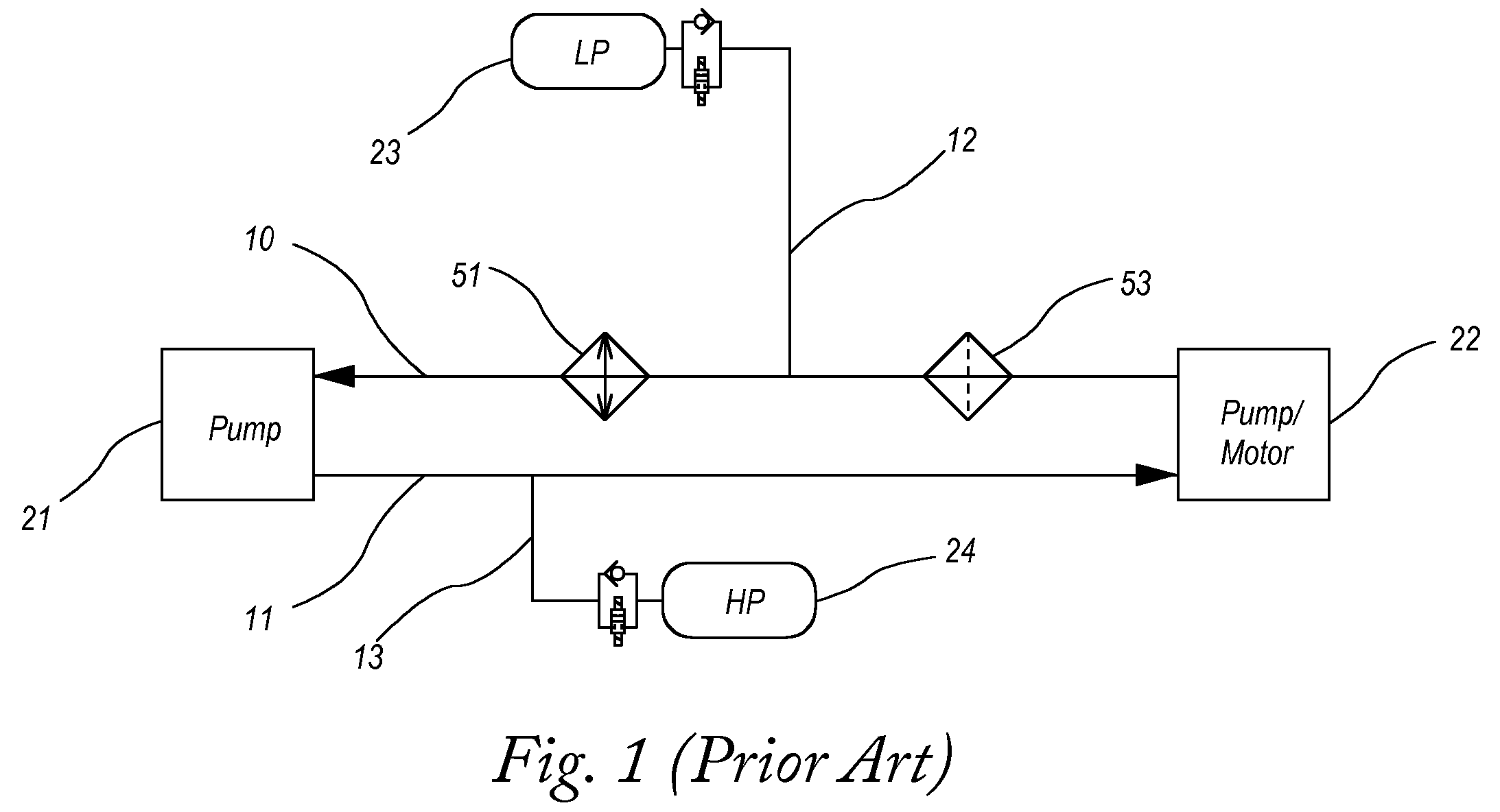
[0041]FIG. 1 shows some primary components that would likely be present in a series hydraulic hybrid vehicle, arranged in a simple hydraulic circuit, but one that is not well optimized for performance. Pump 21 is driven rotationally by an internal combustion engine (not shown), acting to pressurize a working fluid. Drive pump / motor 22 is powered by the working fluid to provide motive power to the vehicle. Fluid processing means includes filter 53 provided for fluid filtration and cooler 51 provided for fluid cooling. Hydraulic fluid paths 10 and 12 ...


PUM


Abstract

A hydraulic manifold has features adapted to the needs of hybrid vehicle applications. In one embodiment, multifunction valves selectively regulate fluid flow among primary and auxiliary flow paths. A normally closed butterfly valve is biased by a relatively small secondary biasing force against rotation in first and second (opposite) directions, and by a relatively large principal biasing force against rotation in the first direction past a transitional angular position at which the principal biasing force takes effect. An actuator selectively controls the transitional angular position and the magnitude of the principal biasing force. In the first direction, flow must overcome only the secondary biasing force to pass the valve. In the second direction, any flow sufficient to overcome the secondary biasing force but not the principal biasing force will divide into a first flow passing the valve and a second flow induced to enter an auxiliary path upstream. Additional flow causing the principal biasing force to additionally be overcome will substantially pass the valve as part of the first flow. This and other embodiments provide a manifold that is controllable to allocate flow among primary and auxiliary paths while remaining responsive to sudden large changes in flow independently of immediate control response.

Description

BACKGROUND OF THE INVENTION[0001]1. Technical Field[0002]Embodiments of the present disclosure are related generally to fluid handling in hydraulic power transmission applications, and in particular to hydraulic fluid manifolds.[0003]2. Description of the Related Art[0004]Hydraulic machines are in common use in a wide variety of industrial and commercial applications. Hydraulic machines transmit power by conducting pressurized fluid between low pressure and high pressure reservoirs. Fluid is typically conducted by means of hoses or pipes joined by one or more fluid conducting manifolds that facilitate their connection. It is also known in the art to provide valve means integrated within the body of such manifolds by which flow may be selectively routed in response to operating conditions.[0005]Typically, the low pressure side of a hydraulic circuit will have one or more manifolds dedicated to handling low pressure flow. Auxiliary functions such as fluid filtration or cooling are als...

Claims


Application Information

Patent Timeline
IPC IPC(8): G05D7/00F16K1/22F15B13/00F15D1/00
CPCG05D7/0641Y10T137/0318Y10T137/0396Y10T137/7771Y10T137/778Y10T137/7878Y10T137/7898Y10T137/7906Y10T137/877
Inventor GRAY, JR., CHARLES L.
Owner THE UNITED STATES OF AMERICA AS REPRESENTED BY THE ADMINISTATOR OF THE U S ENVIRONMENTAL PROTECTION AGENCY EPA
Why Eureka
Try Eureka