
Heat dissipation device

a heat dissipation device and heat dissipation chamber technology, applied in the direction of lighting, heating apparatus, and device details of semiconductor/solid state devices, can solve the problems of occupying a large space of enclosure for cooling fans, irritating users, and distracting users

Inactive Publication Date: 2011-03-31
HON HAI PRECISION IND CO LTD
View PDF6 Cites 4 Cited by
  • Summary
  • Abstract
  • Description
  • Claims
  • Application Information

AI Technical Summary

Benefits of technology

[0005]A conventional heat dissipation device includes a substrate for contacting with a CPU installed in an enclosure of a computer, a plurality of fins extending upwardly from the substrate, and a cooling fan mounted on the fins. The fins are spaced from each other with an air passage defined between every two neighboring fins. The cooling fan provides cooling airflow through the air passages to accelerate heat convection between the fins and the ambient air. However, the cooling fan usually vibrates and makes noise during operation, which may irritate and distract users. Furthermore, the cooling fan occupies a large space of the enclosure, contrary to a desire for compactness in computers.

Problems solved by technology

However, the cooling fan usually vibrates and makes noise during operation, which may irritate and distract users.
Furthermore, the cooling fan occupies a large space of the enclosure, contrary to a desire for compactness in computers.

Method used


Image

  • Heat dissipation device
  • Heat dissipation device
  • Heat dissipation device

Examples


Embodiment Construction

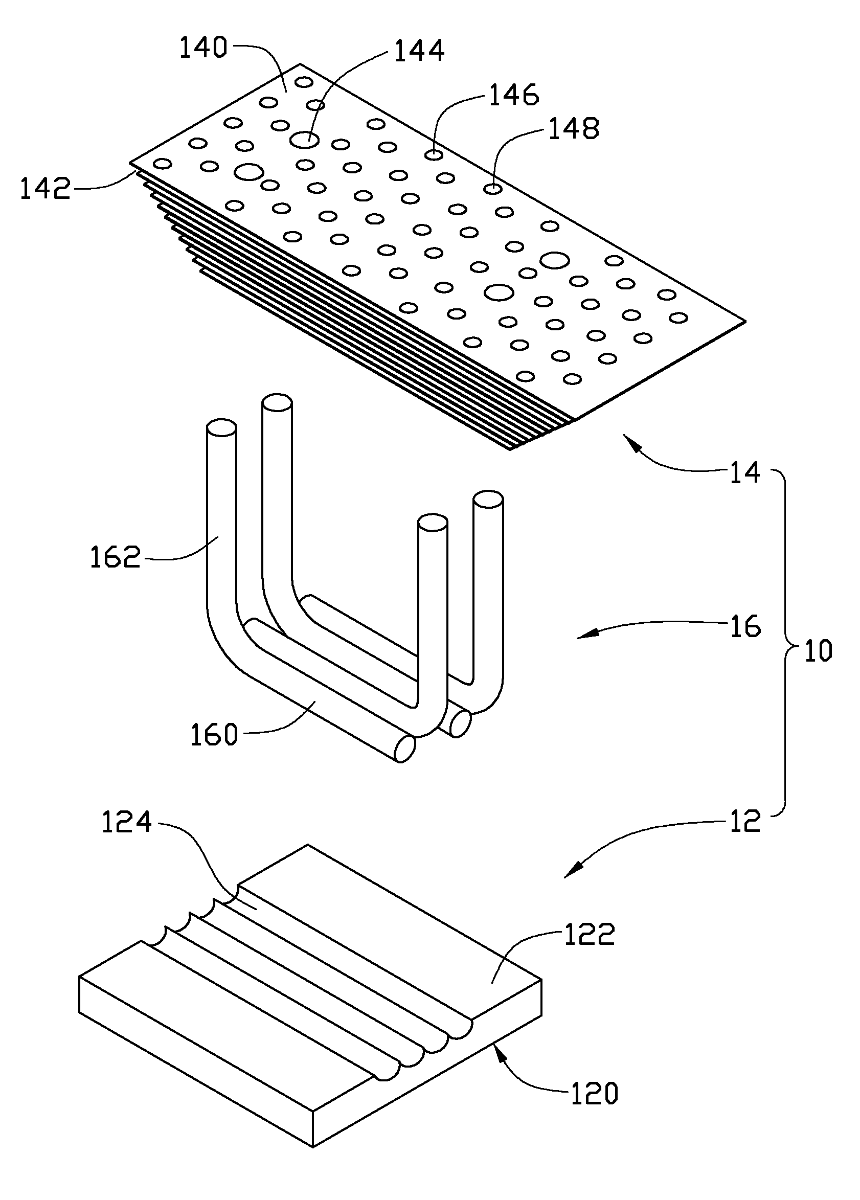
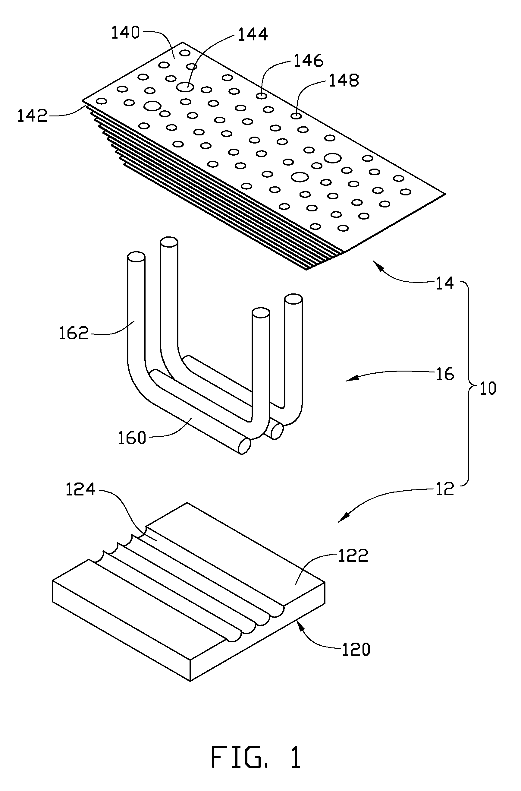
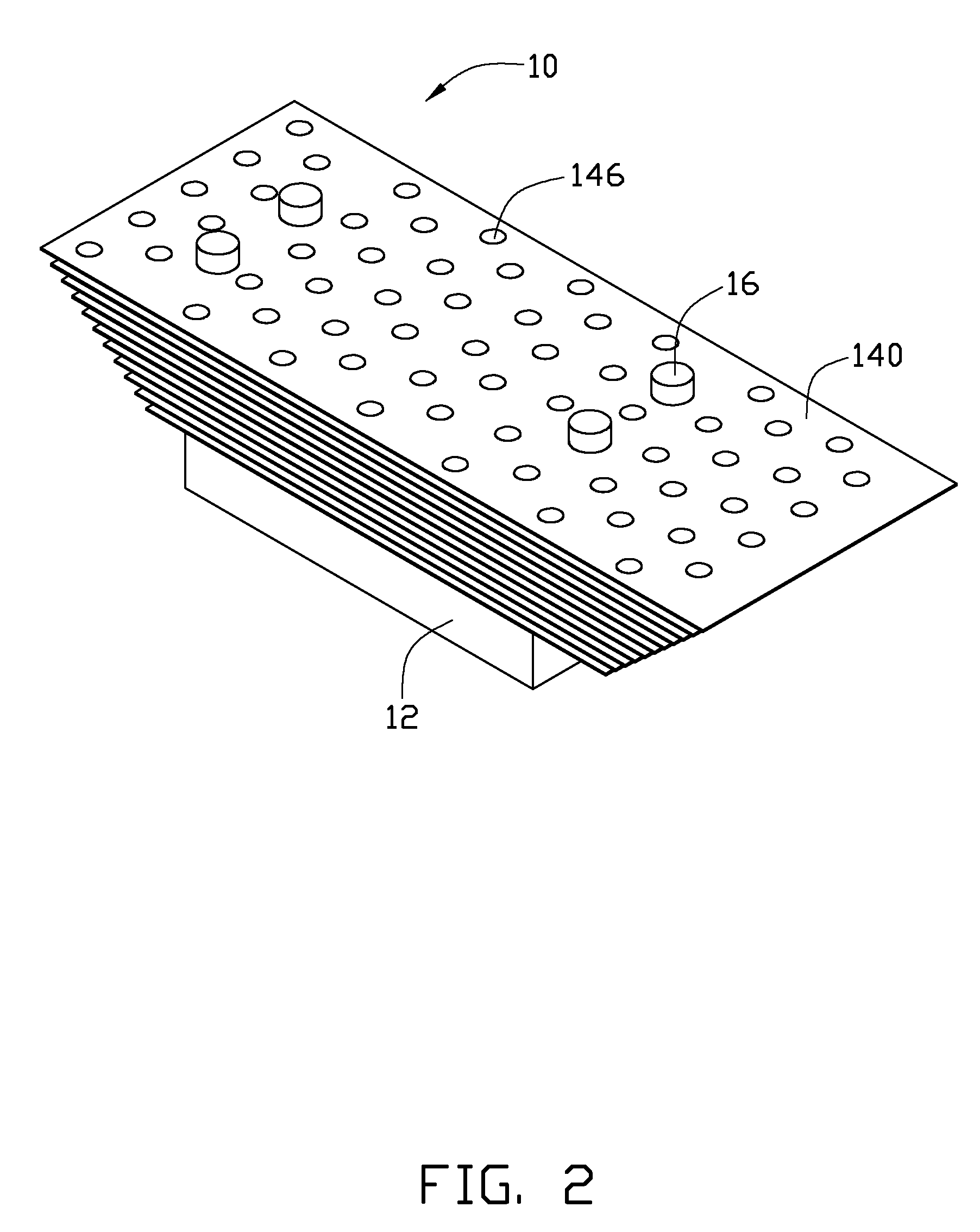
[0010]Referring to FIGS. 1-3, a heat dissipation device 10 in accordance with an exemplary embodiment of the present disclosure is shown. The heat dissipation device 10 includes a substrate 12 for receiving heat from heat-generating components (not shown), a fin assembly 14 located above the substrate 12, and four L-shaped heat pipes 16 connecting the fin assembly 14 with the substrate 12.

[0011]The substrate 12 is made of metal with high heat conductivity coefficient and has a rectangular shape. The substrate 12 includes a planar bottom surface 120 and an opposite top surface 122 facing the fin assembly 14. The substrate 12 defines four elongated parallel grooves 124 in the top surface 122 thereof. The grooves 124 extend from one edge to an opposite edge of the substrate 12. The grooves 124 each are semicircular in cross section. The heat pipes 16 each include an elongated evaporating section 160 and an elongated condensing section 162 substantially perpendicular to the evaporating ...


PUM


Abstract

A heat dissipation device comprises a substrate, a fin assembly located above the substrate and at least one heat pipe connecting the substrate with the fin assembly together. The fin assembly comprises a plurality of fins stacked one above another along a bottom to top direction and space from each other with a gap defined between two neighboring fins. Each of the fins defines a plurality of ventilating holes therein. The ventilating holes of the fins are aligned with each other and form a plurality of vertical air channels in the fin assembly along the bottom to the top direction for ambient air in the gaps flowing therethrough upwardly to escape the fin assembly.

Description

BACKGROUND[0001]1. Technical Field[0002]The present disclosure relates to heat dissipation devices, and particularly to a heat dissipation device for use in an electronic device such as a computer.[0003]2. Description of Related Art[0004]With continuing development of electronic technology, heat-generating electronic components such as central processing units (CPUs) in enclosures of computers are generating more and more heat which requires immediate dissipation. Heat dissipation devices are commonly used to cool the CPUs.[0005]A conventional heat dissipation device includes a substrate for contacting with a CPU installed in an enclosure of a computer, a plurality of fins extending upwardly from the substrate, and a cooling fan mounted on the fins. The fins are spaced from each other with an air passage defined between every two neighboring fins. The cooling fan provides cooling airflow through the air passages to accelerate heat convection between the fins and the ambient air. How...

Claims


Application Information

Patent Timeline
Patent Type & Authority Applications(United States)
IPC IPC(8): G06F1/20F28D15/04F28F7/00
CPCH01L23/3672H01L23/427H01L2924/0002H01L2924/00F28D15/0275F28F1/325
Inventor HUANG, CHAO-JUI
Owner HON HAI PRECISION IND CO LTD
Learn More