
Brake Controller

a technology of brake controller and master cylinder, which is applied in the direction of brake systems, mechanical equipment, transportation and packaging, etc., can solve the problems of master cylinder pressure withstanding capability and measures, affecting the user's experience, so as to prevent abrupt elevation of master cylinder pressure and improve user's feeling. , the effect of improving the user's feeling

Active Publication Date: 2011-03-31
HITACHI ASTEMO LTD
View PDF6 Cites 35 Cited by
  • Summary
  • Abstract
  • Description
  • Claims
  • Application Information

AI Technical Summary

Benefits of technology

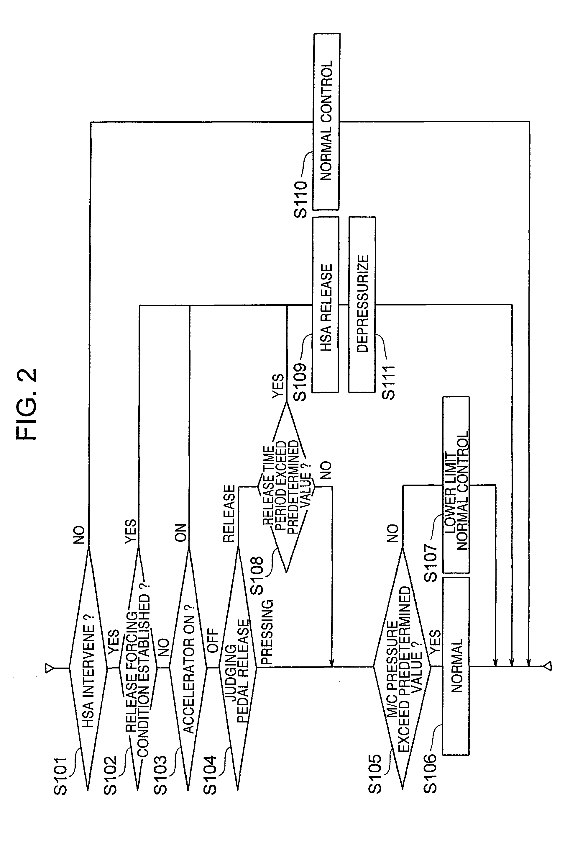
[0004]An object of the present invention is to provide a brake controller which improves user's feeling caused upon pressing of a brake pedal during fluid pressure holding, prevents abrupt elevation of a master cylinder pressure caused due to the minute brake pedal manipulation, and allows a fluid pressure change according to a manipulation to make it possible provide a manipulation like a normal brake. According to the invention, a brake controller comprises, an accelerator opening degree detecting means for detecting a pressing amount of an accelerator pedal, an input piston moving in accordance with a movement of a brake pedal, an assist piston moved by an electric motor, a master cylinder for generating a pressure of brake fluid in accordance with movements of the input piston and the assist piston, a slope climbing vehicle stopping detecting means for judging as to whether or not a vehicle is in stoppage during its slope climbing, a controller for controlling the electric motor, and a pedal release detecting means for detecting a release of the brake pedal, wherein when the slope climbing vehicle stopping detecting means decides that the vehicle is in stoppage during its slope climbing, and the pedal release detecting means detects that the brake pedal is released, the controller controls the electric motor to move the assist piston so that an amount of pressure decrease of the brake fluid caused by the movement of the input piston with the release movement of the brake pedal is compensated with the movement of the assist piston to restrain the pressure of brake fluid in the master cylinder from being decreased.

Problems solved by technology

However, in the art described in JP-A-2006-306350, there are problems that a heating of the fluid actuator will be caused due to holding of a high fluid pressure which is required for vehicle stop and bad feeling will be suffered upon driver's pressing of a brake pedal during the fluid pressure holding.
As a result, reconsideration for master cylinder pressure withstanding capability and measures for switching to control are required.

Method used


Image

  • Brake Controller
  • Brake Controller
  • Brake Controller

Examples


Embodiment Construction

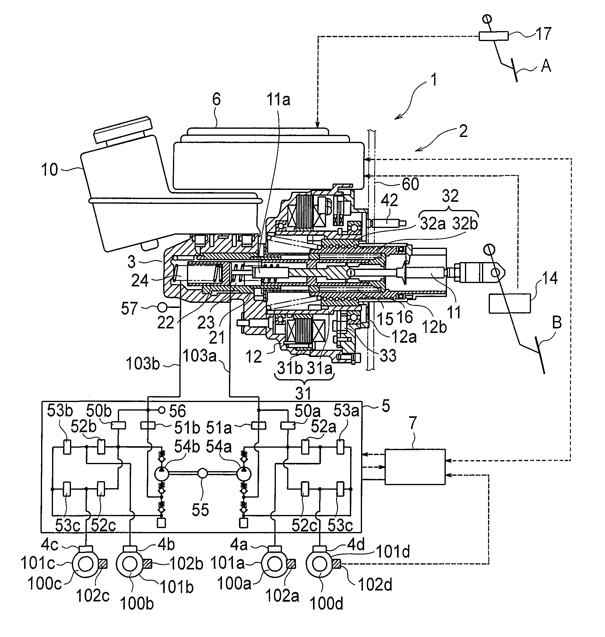
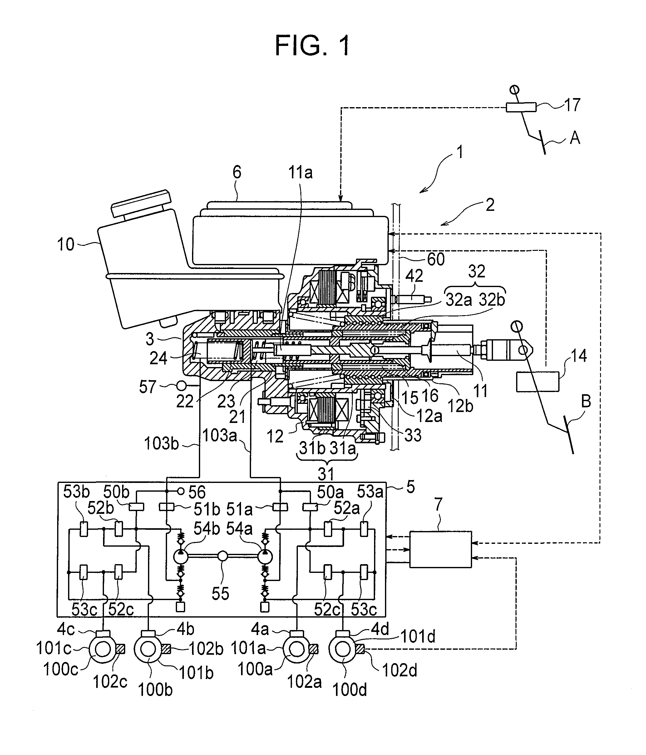
[0011]In the following, a brake controller for use in vehicles according to the present invention will be described with reference to FIGS. 1 to 4. FIG. 1 is a system block diagram showing one structural example of a brake controller for vehicle use according to one embodiment of the present invention.

[0012]In a vehicle brake apparatus 1 as a brake controller, a brake assistor 2, in response to an operation amount of a brake pedal B and a condition of vehicle travel a brake assisting device 2 controls a fluid pressure of a braking fluid caused by a master cylinder 3 based on a direction causing increase or decrease in operation force of the brake pedal B, and supplies a fluid pressure control unit 5 with the brake fluid having the thus-controlled fluid pressure.

[0013]In this embodiment, the fluid pressure of the braking fluid generated in the master cylinder 3 is transmitted to the fluid pressure control unit 5, and the fluid pressure of the braking fluid is further transmitted from...


PUM


Abstract

In a brake controller, a slope climbing vehicle stop detecting means determines when the vehicle is stopped while climbing a slope, and a pedal release detecting means determines that the pedal is released. An assist control unit interpolates a decrement in brake fluid pressure in the master cylinder due to an input piston movement caused by a release of a brake pedal. An assist piston is controlled by an electric motor to restore and maintain the fluid pressure within the master cylinder.

Description

BACKGROUND OF THE INVENTION[0001]The present invention relates to a brake controller for controlling a vehicle brake.[0002]As a conventional function for assisting a restart of a slope climbing, there are a wheel cylinder pressure keeping with a fluid actuator and a parking brake utilization, as described in for example, JP-A-2006-306350.BRIEF SUMMARY OF THE INVENTION[0003]However, in the art described in JP-A-2006-306350, there are problems that a heating of the fluid actuator will be caused due to holding of a high fluid pressure which is required for vehicle stop and bad feeling will be suffered upon driver's pressing of a brake pedal during the fluid pressure holding. In a fluid pressure booster using an electric motor, if a wheel cylinder pressure is held a master cylinder pressure is abruptly elevated even with a minute brake pedal manipulation due to sealing of a brake fluid within the master cylinder. As a result, reconsideration for master cylinder pressure withstanding cap...

Claims


Application Information

Patent Timeline
Patent Type & Authority Applications(United States)
IPC IPC(8): B60T13/66B60T7/04B60T13/74
CPCB60T7/042B60T13/142B60T2201/06B60T13/686B60T7/122B60T13/662
Inventor MATSUZAKI, NORIKAZUINNAMI, TOSHIYUKINISHINO, KIMIOKIKAWA, MASAYUKI
Owner HITACHI ASTEMO LTD
Learn More