

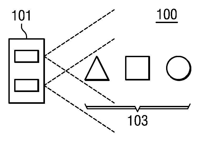
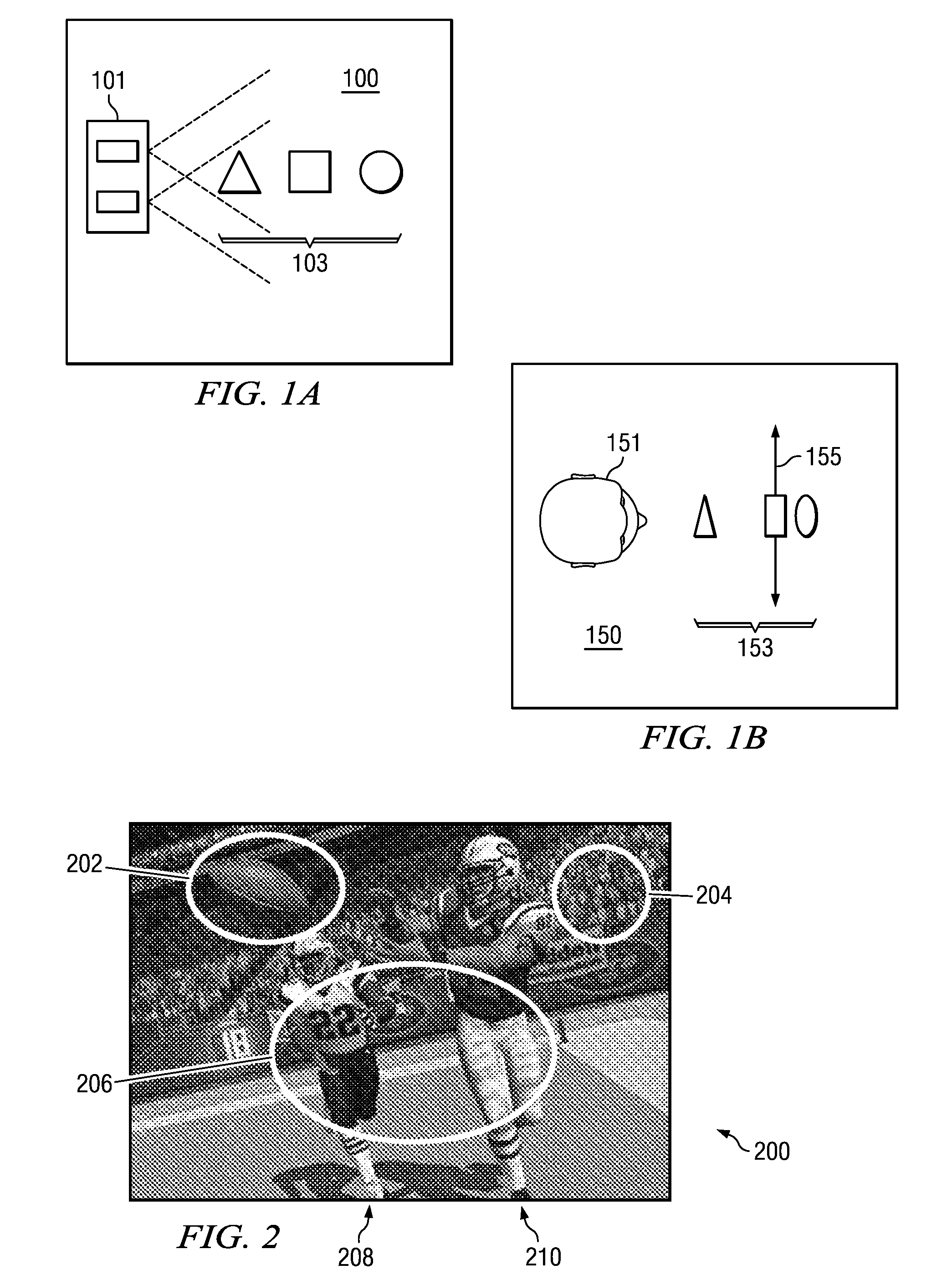
Point reposition depth mapping
a depth mapping and point repositioning technology, applied in image enhancement, instruments, sport apparatus, etc., can solve the problems of both compressed and distorted perception depth, and achieve the effect of optimizing stereoscopic imag
- Summary
- Abstract
- Description
- Claims
- Application Information
AI Technical Summary
Benefits of technology
Problems solved by technology
Method used
Image

Examples
first embodiment
of a Scaling Solution Z′(Z)
[0086]Equation 35 can be expressed as:
(Zσ(Z′))·ZZ′=γ·σ(Z′)Z.(Equation36)
[0087]From Equation 36, Equation 37 may be derived:
σ(Z′)=α1+βZ′where:α=E·s(E-D)andβ=W·A·f(E-D)·c.(Equation37)
[0088]Substituting this expression into Equation 36 gives:
β·Z′Z′·(Z′+β)=γ·ZZ(Equation38)
which, when integrated, gives:
ln(Z′)−ln(Z′+β)=γ·ln(Z)+∞ (Equation 39)
where κ is a constant of integration.
[0089]Equation 39 can be solved to yield an embodiment of a solution for a scaling solution:
Z′(Z)=β(K·Z-γ-1)(Equation40)
where K is a constant related to κ.
[0090]To complete the solution, the constants γ and K are determined by applying the disparity limit conditions:
Zmax=β(K·Zmax-γ-1)andZmin=β(K·Zmin-γ-1).(Equation41)
[0091]Solving these for γ and K and back substituting for β (Equation 37) and then for A and B (Equations 8 and 9), the following scaling solution that delivers the desired optimal depth mapping profile is derived:
Z′(Z)=β(K·Z-γ-1)where:β=(Dmax-Dmin)·(Zmin·Zmax)[E·(Zmax-Zmin)...
second embodiment
of a Scaling Solution Z′(Z)
[0092]In another embodiment, an alternative scaling solution or point reposition depth mapping function Z′(Z) may be used. This alternative embodiment point reposition depth mapping function is defined as follows:
Z′(Z)=(α·ln(Z+β)+B)·β1-α·ln(Z+β)-B,whereβ=(Dmax-Dmin)·(Zmin·Zmax)[E·(Zmax-Zmin)-Dmax·Zmax+Dmin·Zmin],whereα=β·(Zmin-Zmax)ln[(Zmin+β)Zmax+β)]·[(Zmin+β)·(Zmax+β)],whereB=ZminZmin+β-α·ln(Zmin+β),
where Z is an initial model point location from a left-eye or a right-eye observation point, where
Z=(xyz),
and where E is eye separation. (Equation 43).
[0093]This mapping may be a desirable choice in cases where automated correction of depth is desired, such as in computer gaming scenarios or for automated CGI stereoscopic rendering.
[0094]In yet another embodiment, the point reposition depth mapping function may be implemented using a look up table, where predetermined values for Z′(Z) are located in the table based upon input parameters. Such a look up table ...
PUM
 Abstract
Description
Claims
Application Information