Filter part for fluid lines

a technology of fluid lines and filter parts, applied in separation processes, filtration separation, transportation and packaging, etc., can solve problems such as material fatigue, and achieve the effect of minimal pressure loss

Active Publication Date: 2016-09-20
WEH INC
View PDF11 Cites 0 Cited by
  • Summary
  • Abstract
  • Description
  • Claims
  • Application Information

AI Technical Summary

Benefits of technology

[0015]It is therefore the object of the invention to avoid the disadvantages according to the state of the art, and to provide a filter part for fluid lines in particular which offers the largest possible filter area over the smallest possible overall size, while simultaneously ensuring the optimal flow rate with the defined particle filter rate and minimal pressure loss. The filter area is thus optimised for the required gas flow rate.
[0018]The filter component in accordance with the invention is further characterized by high filter fineness in combination with compact design, very good pressure resistance and high flow rates. In particular, there is resistance against differential pressures and puncturing of up to 900 bar.
[0021]It is especially preferred if the filter screen or filter mesh comprises at least two filter layers which are arranged one on top of the other, especially three or more filter layers arranged on top of each other. The stacking of filter layers leads to the advantage that layers with different filter mesh widths can be arranged on top of each other, e.g. the mesh width of the filter layers decreases from the base body to the outside, or vice versa. The filter layers can also comprise different materials. The arrangement with several filter layers ensures that large particles are retained at first in the first filter layer for example, slightly smaller ones in the next layer and very small ones in the last filter layer for example. Very good filtering can thus be achieved by the multilayer configuration. It is a further advantage that in the case of a three-layer configuration the first and third layer can substantially act as a supporting fabric and the intermediate layer acts as the actual filter mesh or filter screen. The layers used as supporting fabric can have larger mesh widths than the filter mesh, e.g. mesh widths of more than 400 μm or at least larger than 100 μm. The supporting fabric is then used for preliminary filtering and increases the backflushing capability and thus further increases the operational lifespan of the filter part.
[0028]In particular the line or the supply hose, respectively, is also to allow a reliable conduction of gaseous media such as natural gas or hydrogen at very high pressures of greater than 150 bar, in particular greater than 200 bar, preferably greater than 400 bar, in particular in the range of 150 bar to 400 bar, preferably 200 bar to 350 bar, in particular 200 bar to 250 bar. Furthermore, it is also to be durable during refueling at low temperatures in the range of −50° C. to +120° C., preferably −40° C. to +85° C. Further requirements are low weight, small dimensions, and easy handling capability. In particular, the line is to allow a refueling device having simple construction, which can be operated by customers similarly to conventional refueling devices for liquid fuels.

Problems solved by technology

WO 02 / 00322 A1 describes the use of filter elements, especially metal fabrics and metal braiding, as disadvantageous for the use in filling nipples with filling pressures of up to 875 bar and more, since they are sensitive to compressive loading or alternating loads which can lead to material fatigue.
U.S. Pat. No. 4,442,003 does not provide information on the filter mesh width and the filter configuration.

Method used


Image

  • Filter part for fluid lines
  • Filter part for fluid lines
  • Filter part for fluid lines

Examples


Embodiment Construction

[0034]The invention relates to a filter part for fluid lines, preferably high-pressure lines with pressures in the range of 150 to 900 bar, preferably in the range of 200 to 350 bar, more preferably in the range of 700 to 875 bar, for use especially in filling nipples, non-return valves, pressure regulators, cylinder valves, filling couplings, switching valves, break-off safety devices, quick couplings and also as a separate filter part. The filter part comprises a base body and at least one fluid passage opening, wherein the base body and the fluid passage opening are covered by at least one filter element. The invention further relates to a method for producing a filter part with a base body and a filter element, especially in form of a screen filter which is also known as a filter mesh.

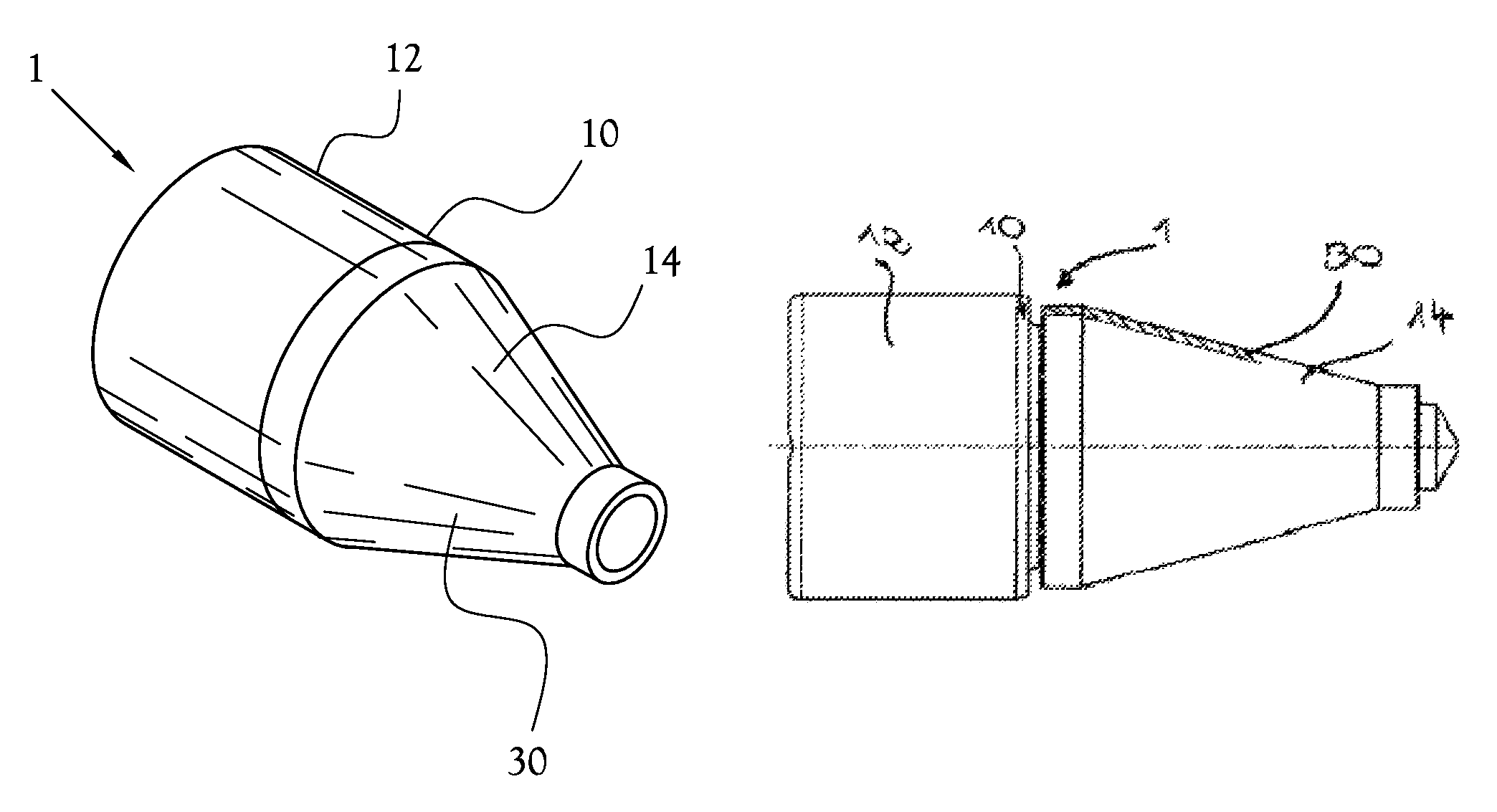
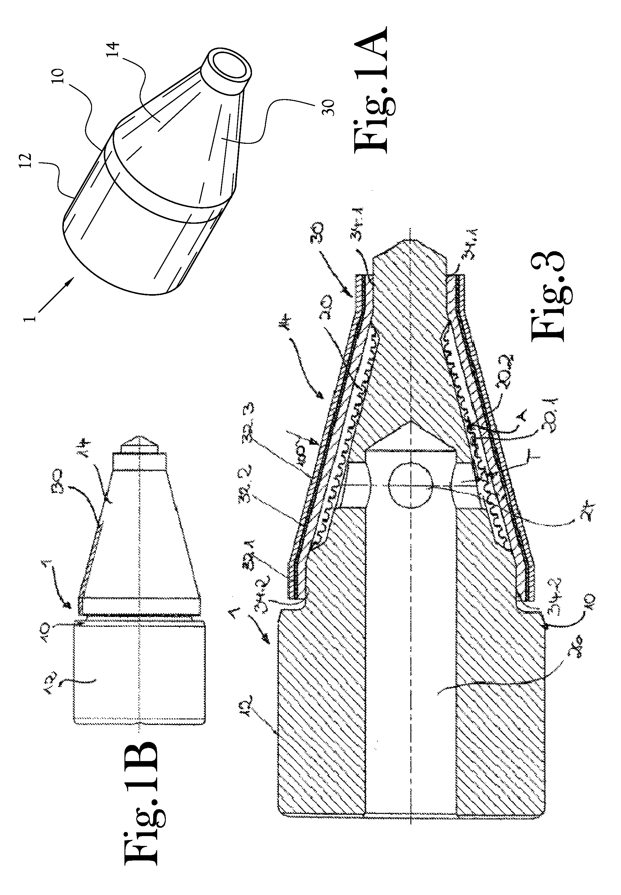
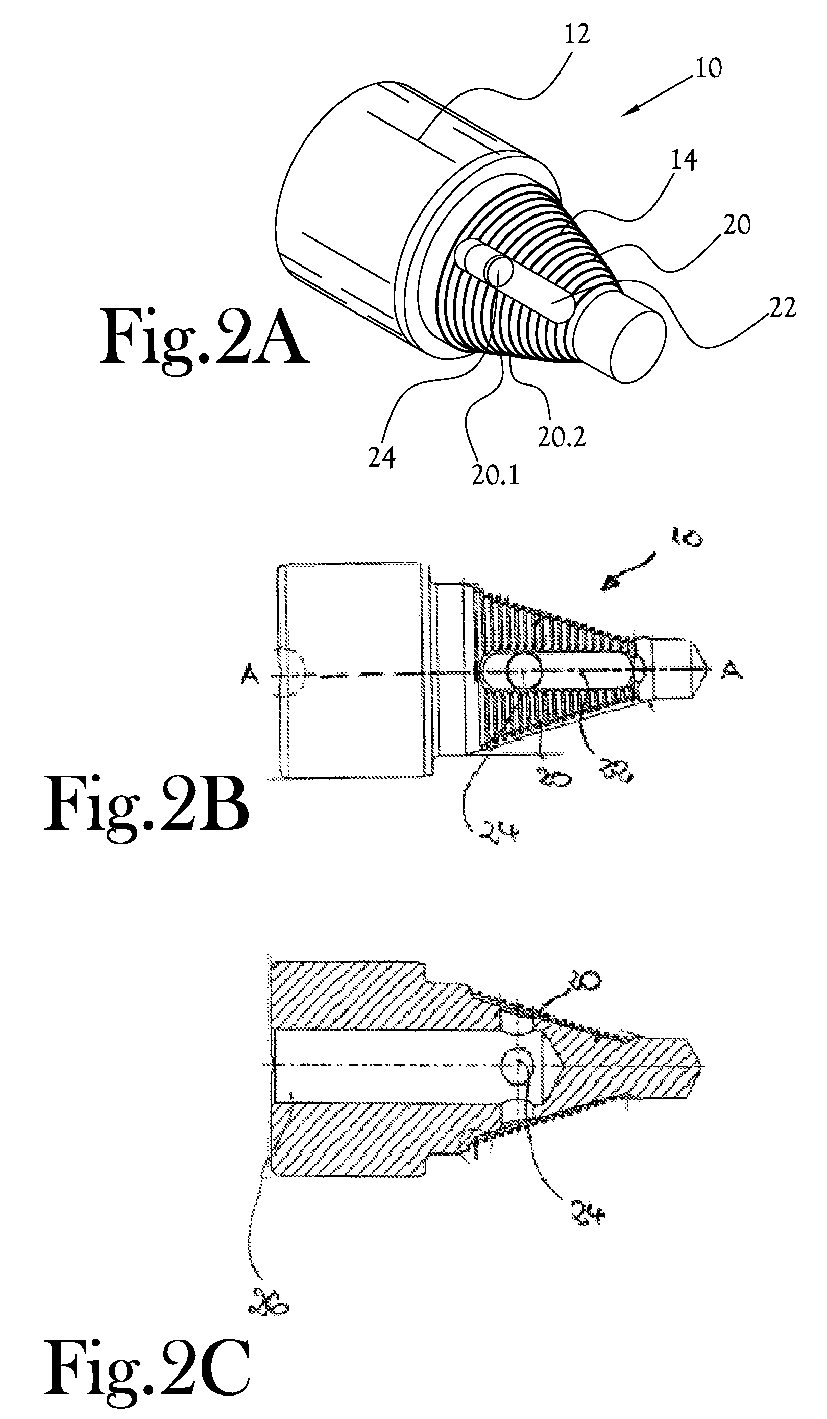
[0035]FIGS. 1a-1b shows a base body 10 with a filter mesh or filter screen 30 arranged thereon, thus producing the filter part 1. FIG. 3 shows a sectional view of the filter part 1 for a fluid line...


PUM

PropertyMeasurementUnit
pressuresaaaaaaaaaa
widthaaaaaaaaaa
widthaaaaaaaaaa

Abstract

A filter part for fluid lines, preferably high-pressure lines with pressures in the range of 150 to 900 bar, preferably in the range of 200 to 350 bar, more preferably in the range of 700 to 875 bar, for use especially in filling nipples, non-return valves, pressure regulators, cylinder valves, filling couplings, switching valves, break-off safety devices, quick couplings and also as a separate filter part. The filter part comprises a base body and at least one fluid passage opening, wherein the base body and the fluid passage opening are covered by at least one filter element. The invention further relates to a method for producing a filter part with a base body and a filter element, especially in form of a screen filter which is also known as a filter mesh.

Description

CROSS-REFERENCE TO RELATED APPLICATIONS[0001]This Application is a continuation of PCT / EP2012 / 004692 filed on Nov. 9, 2012, which claims the benefit of DE 10 2011 118 632.1, filed Nov. 14, 2011, which content is incorporated herein by reference.STATEMENT REGARDING FEDERALLY SPONSORED RESEARCH OR DEVELOPMENT[0002]Not Applicable.BACKGROUND OF THE INVENTION[0003]1. Field of Invention[0004]The invention relates to a filter part for fluid lines, for use especially in filling nipples, non-return valves, pressure regulators, cylinder valves, filling couplings, switching valves, break-off safety devices, quick couplings and also as a separate filter part.[0005]2. Description of the Related Art[0006]The invention relates to a filter part for fluid lines, preferably high-pressure lines with pressures in the range of 150 to 900 bar, preferably in the range of 200 to 350 bar, more preferably in the range of 700 to 875 bar, for use especially in filling nipples, non-return valves, pressure regul...

Claims


Application Information

Patent Timeline
Patent Type & Authority Patents(United States)
IPC IPC(8): B01D46/00B01D29/15B01D39/10B01D35/02
CPCB01D39/10B01D29/15B01D35/023B01D46/0012B01D46/0017B01D46/0023Y02E60/321Y10T29/49826Y02E60/32B01D46/62
Inventor WEH
Owner WEH INC
Why Eureka
Try Eureka